
Welcome to
Azur Electronics
Azur Electronics
HP 3763A ERROR DETECTOR
Home
Projects
Test Equipment
- Accessories
- Adaptors
- Amplifiers
- Attenuators
- Cables
- Frequency Counters
- Logic Analysers
- Multi-Meters
- Network Analysers
- Oscilloscopes
- Power Meters
- Power Supplies
- Prototyping Equipment
- Signal Generators
- Spectrum Analysers
- Tools
Operating Information
- Operating HP 141T
- Operating HP 1630D
- Operating HP 8175A
- Operating HP 8407A
- Operating HP 8410C
- Operating HP 8552B IF Section
- Operating HP 8553B RF Section
- Operating HP 8554B RF Section
- Operating HP 8555A RF Section
- Operating HP 8556A LF Section
- Operating HP 8594E Spectrum Analyser
- Operating HP 8901B
- Operating LeCroy 9310
Technical
- Allen Key Sizes
- High Voltage Measurement
- HP Cases
- HP Information
- HP-IB Interface Bus
- Measurement Units
- Motorola ECL
- RF Connectors
- RF Power - Voltage Conversion
For Sale
Wanted
Links
About Me
Contact Me
Site Map
I bought this HP 3763A Error Detector for spares or repair on eBay. The original cost was $9,125 in 1980. This version was made for British Telecom to test 68 & 140Mbit/s transmission systems. The BT reference is "Tester No 274A/HPU/1" and is HP option H43. Together with the HP 3762A Data Generator, this forms a dedicated error rate measurement system for evaluating high speed digital transmission systems.
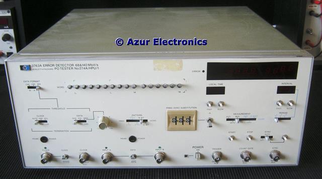
Front view
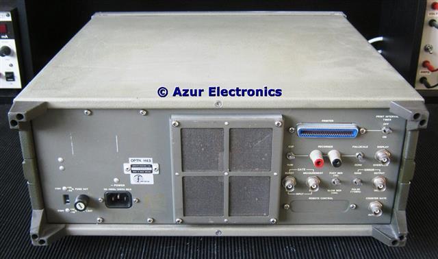
Rear view with additional connections
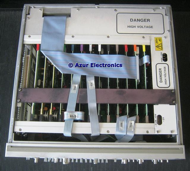
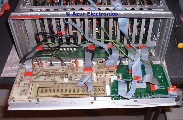
Top view with cover removed
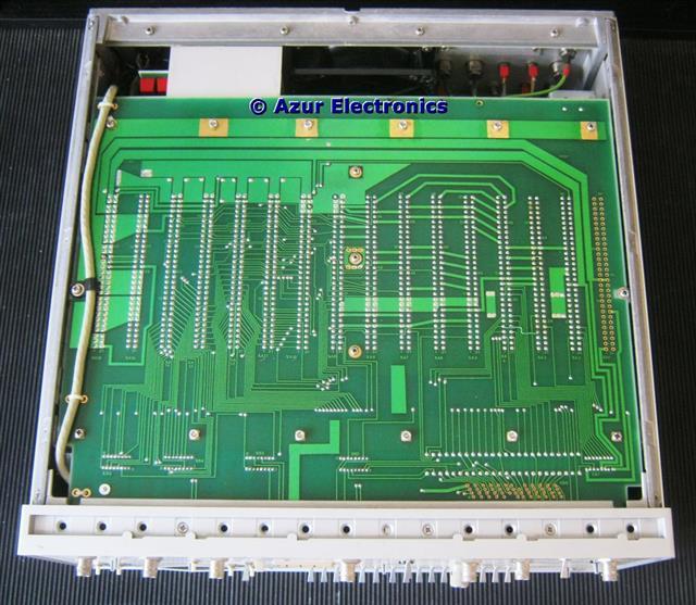
Bottom view with cover removed
October 2010
The 3763A arrived in a very clean and complete state. Completely stripped down to assembly level and visually checked then cleaned. Apart from all the internal ribbon and coaxial cabling it is easy to dismantle. As usual, all the stickers and labels take a while to completely remove.
The 3763A arrived in a very clean and complete state. Completely stripped down to assembly level and visually checked then cleaned. Apart from all the internal ribbon and coaxial cabling it is easy to dismantle. As usual, all the stickers and labels take a while to completely remove.
Front panel hinged down
All reassembled and powers-up ok. Testing is held up by needing the Operating and Service Manuals for the 3762A - 3763A combination. These should make a useful data generator and analyser system, plus by using an external transmitter clock it can be used over a very wide frequency range.
January 2011
Download Operating Manual for 3762A and 3763A.
August 2015
Fails Operator's Checks so more work required.
March 2017
Have finally obtained the Service Manual, big thanks to Dave at Artek Manuals who managed to buy the Manual and specially scanned it for me, all 396 pages!
April 2017
Started testing and fails Operator's Checks as before. Some repair work is therefore required. For details see Repair HP 3763A Error Detector.
Converted the front panel connections: Clock Input; Input A; from 75Ω to 50Ω. The Trigger Output was already 50Ω. Input B needs further investigation.
October 2019
Completed repairs and evaluation. The 3763A is an error detector that operates between 1kHz to 150MHz plus, together with the 3762A.
July 2020
As I have very limited use for this, trying to decide whether to sell or keep the 3763A. Complete with .pdf Operating & Service Manuals. It would be a pity to dismantle it and there are lots of hard to find ECL parts in the 3763A.
Some further testing revealed a few minor issues.
March 2021
I have decided to keep the 3763A, mainly as it is paired with the 3762A, although I rarely require data error detection facilities. It is a lot of 'electronics' and one day I might just need it for a project.
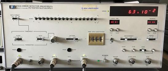
Front panel connections
FRONT PANEL CONNECTIONS
Clock Input: 1kHz to 150MHz, 50Ω (Modified), 300mVpp to 3Vpp max.
Green LED indicates clock transitions present.
External clock can only be used with binary data inputs.
Clock Output: ECL, 50Ω to -2V or GND.
50% duty cycle on recovered clock.
Input A: CMI/RZ/NRZ, 50Ω (Modified), 3Vpp max, Normal or Inverted, or ECL.
Green LED indicates data transitions present.
Input B: CMI data only.
Trigger Output: one pulse every sequence or word, 50Ω, 1Vpp min.
Every 16-bits in 10101 pattern and every 8 bits in ALT mode.
Position is determined by Word A switches and is 2-bits wide.
Count Gate Input: ECL, 50Ω, high level enables count.
Sync Input: ECL, 50Ω, high level causes resync.
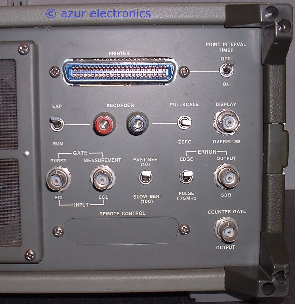
Rear panel connections
REAR PANEL CONNECTIONS
Printer: 8421 BCD 10 columns.
Recorder Output: Constant current driver with nominal 500ms minimum response. FSD 1mA into 10KΩ max.
Display Overflow: Signal from MSD. 1Vpp 50Ω.
Burst Gate Input: Disables external clocks for burst mode operation.
ECL, 50Ω, high level disables clock.
Measurement Gating Input: Gates error and clock inputs to provide a measurement window. ECL, 50Ω, high level gates measurement off.
Error Output: 1 transition or pulse per error. 1Vpp 50Ω.
Counter Gate Output: Error counter gating period for external counter.
TTL, output low during gating period, output high between gating periods.
ERROR DETECTOR FUNCTION
The output from the device or system under test is compared bit by bit with an independent, error free reference pattern. Synchronisation can be automatic, manual, or by external control. Errors are displayed in BER (Bit Error Rate), or COUNT formats. In BER mode, a reading is given after 10 or 100 errors are counted. In COUNT mode, the gating period can be selected internally, externally, or manually.
Using the Interval Timer, the gating period can be set from 1 minute up to 24 hours. Clock recovery from CMI data is provided at the rates of the installed crystal clocks with equalisation to compensate for up to 12dB of loss. Frequency offset can also be measured.
For long term error measurements and more detailed study of error distribution, etc., error, printer and recorder outputs are provided, together with a time of day clock and an interval timer. With this results can be printed out at the end of every gating period, or at selected intervals, together with the time of day.
[HP Data Sheet]
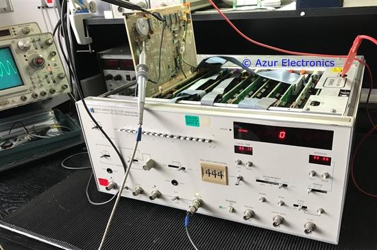
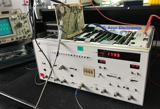
Testing Input B with CMI data, gating ok and no errors.
No clock input is required as recovered from CMI data.
No clock input is required as recovered from CMI data.
Testing Input B with CMI data, gating ok
and errors introduced deliberately in 3762A.
and errors introduced deliberately in 3762A.
The are some subtle and undocumented differences between the HP standard version and this BT special version of the 3763A. This has meant that the test procedure is different in some repects to the Service Manual.
Now considered to be tested ok.
Now considered to be tested ok.