
Welcome to
Azur Electronics
Azur Electronics
OPERATING HP 8901B
MODULATION ANALYSER
MODULATION ANALYSER
Home
Projects
Test Equipment
- Accessories
- Adaptors
- Amplifiers
- Attenuators
- Cables
- Frequency Counters
- Logic Analysers
- Multi-Meters
- Network Analysers
- Oscilloscopes
- Power Meters
- Power Supplies
- Prototyping Equipment
- Signal Generators
- Spectrum Analysers
- Tools
Operating Information
- Operating HP 141T
- Operating HP 1630D
- Operating HP 8175A
- Operating HP 8407A
- Operating HP 8410C
- Operating HP 8552B IF Section
- Operating HP 8553B RF Section
- Operating HP 8554B RF Section
- Operating HP 8555A RF Section
- Operating HP 8556A LF Section
- Operating HP 8594E Spectrum Analyser
- Operating HP 8901B
- Operating LeCroy 9310
Technical
- Allen Key Sizes
- High Voltage Measurement
- HP Cases
- HP Information
- HP-IB Interface Bus
- Measurement Units
- Motorola ECL
- RF Connectors
- RF Power - Voltage Conversion
For Sale
Wanted
Links
About Me
Contact Me
Site Map
December 2014
The HP 8901B Modulation Analyser can measure RF signal frequency, frequency drift, power level (broadband and off-channel), amplitude modulation, frequency modulation, phase modulation, AM and FM noise components. It recovers the modulating signal and can measure the audio signal's frequency and distortion. Automatic operation from front panel keys or HPIB is achieved, plus some sophisticated keyed 'special code' measurements are available.
The HP Operating and Calibration Manual provides detailed information on all the various measurements that the 8901B can make and from page 65, the Basic Operation and Applications Guide provides procedures for checking all the functions.
The 8901B is a fairly complex and versatile beast, so these are my working notes.
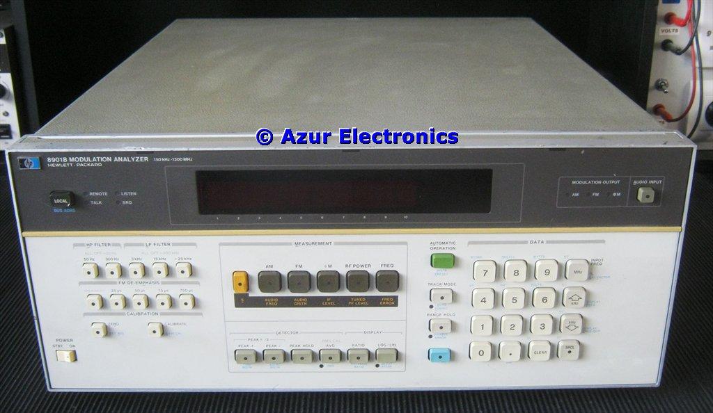
HP 8901B Front Panel
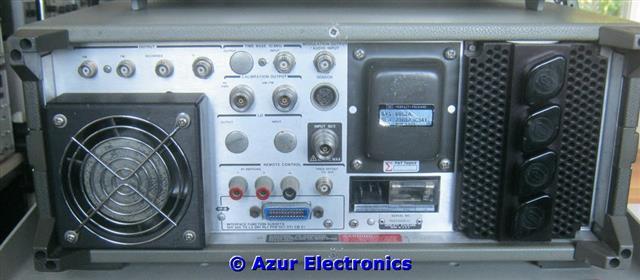
HP 8901B Rear Panel
This 8901B has Option 001 which means all the connectors are at the rear.
The connection to the RF Input can be used for all measurements including RF Power, although uncalibrated. The Sensor Input can be used with the 848x series of Power Sensors which provide a calibrated and extended measurement capability, see Power Meters for further details.
The Time Base 10MHz Input can be used with a TCXO 10MHz >0.5Vpp source for improved accuracy. The 8901B automatically detects if this is available for use. Pressing 15.1 SPCL (Special Function) keys will display 0 if the internal timebase is being used, or 1 if the external timebase is being used. The SPCL key LED is on for a few seconds then the display returns to the previous setup.
Power Up & Low Level
On Power Up, all the LED Displays are lit for approximately 10 seconds, then the Display goes to 2 dashes & MHz if no signal input is connected. This display also indicates that the input signal is too low to be detected, typically <-30dBm or 1µW.
The input specification is:
The input specification is:
| 150kHz to 650MHz | +30dBm to -25dBm |
| 650MHz to 1300MHz | +30dBm to -20dBm |
Measuring
This Display of 4 dashes indicates that the µP is setting up a measurement.
FREQUENCY MEASUREMENTS
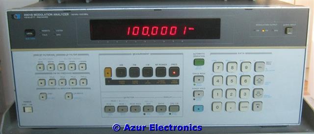
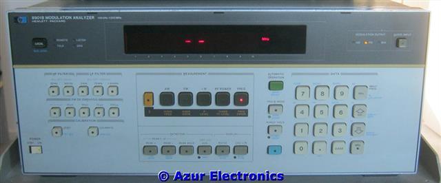
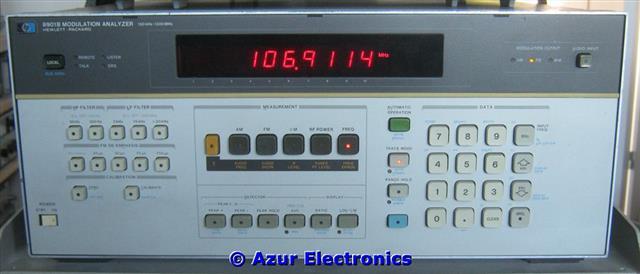
100MHz Frequency, 7 Digit Display
Connecting a RF Input of 100MHz at 0dBm (with no modulation) and pressing the FREQ and AUTOMATIC OPERATION keys (default setting on Power Up) and the Display indicates 100MHz with 100Hz resolution.
The accuracy of this measurement depends on the signal source and the timebase. Using an external 10MHz TCXO will improve the counters accuracy.
The accuracy of this measurement depends on the signal source and the timebase. Using an external 10MHz TCXO will improve the counters accuracy.
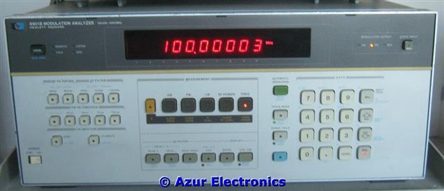
10Hz Resolution, 8 Digit Display
The resolution of the frequency counter can be improved to 10Hz by pressing 7.1 SPCL (Special Function) keys. The SPCL key LED is now on. This can be reset by pressing the AUTOMATIC OPERATION key.
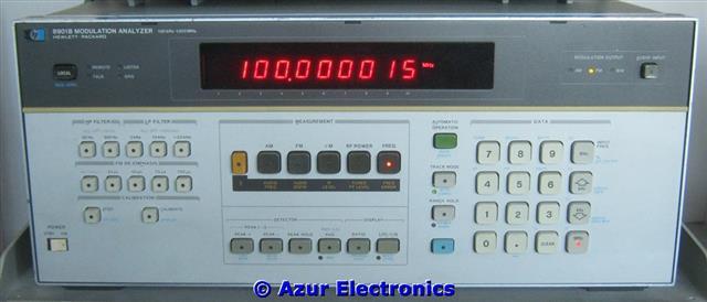
1Hz Resolution, 9 Digit Display
The resolution of the frequency counter can be improved to 1Hz by pressing 7.4 SPCL (Special Function) keys. The SPCL key LED is now on. This can be reset by pressing the AUTOMATIC OPERATION key.
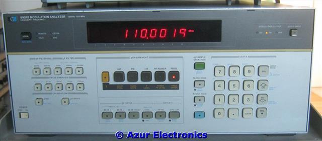
110MHz, Manual Tuning
Manual tuning is available by entering the desired frequency and MHz, in this case by pressing 110 MHz keys. This is useful if there are multiple signals or harmonics and you want to choose one of them. Automatic operation would select the signal with the greatest amplitude. If the signal is out of frequency range error code 01 will be displayed.
107MHz, Track Mode
Track mode is available by pressing the TRACK MODE key, the 8901B is now locked to the input signal. This is useful if the signal is drifting or noisy. Track mode can also be used with automatic operation where there is a single signal which is drifting or noisy.
Frequency Error
Frequency error can be measured by first manually tuning to the desired frequency, then by pressing the gold S (Shift) and FREQ ERROR keys. The difference between the 2 frequencies is displayed, positive if input frequency is higher and negative if input frequency is lower.
To reset to the power up condition, press the blue (Shift) and INSTR PRESET keys.
To reset to the power up condition, press the blue (Shift) and INSTR PRESET keys.
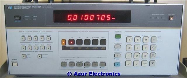
10Hz Frequency, 8 Digit Display
The minimum frequency for an RF input is 150kHz. This can be extended down to 20Hz by using the audio counter. Connect the signal source to the AUDIO INPUT connector and press the AUDIO INPUT key, then press the gold S (Shift) and AUDIO FREQ keys. The 3 key LEDs will remain on. The audio counter has a range of 20Hz to 250kHz. In this case, a minimum frequency of just over 10Hz was achieved.
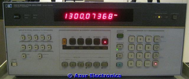
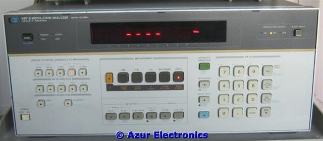
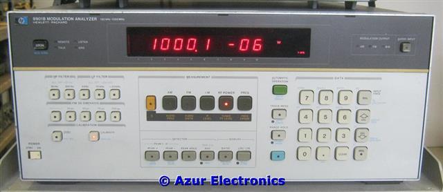
1,300MHz Frequency, 9 Digit Display with 100Hz Resolution
The maximum frequency for an RF input is 1300MHz. Over this Error 10 is displayed. The maximum frequency could be extended by an external down-converter, but in practice it is easier to use a separate frequency counter.
January 2015
RF POWER MEASUREMENTS
Uncalibrated
Uncalibrated
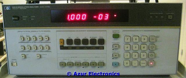
1.000mW Power, 4 Digit Display
Uncalibrated RF power measurements can be made by connecting the signal source to the RF input. First measure the frequency in automatic or manual mode, then press the RF POWER key.
In this case, the display reads 1.000 -03 W indicating 1 x 10⁻³ Watts or 1.000 mW.
In this case, the display reads 1.000 -03 W indicating 1 x 10⁻³ Watts or 1.000 mW.
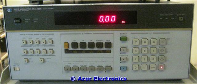
0.00dBm Power, 3 Digit Display
Pressing the LOG/LIN key switches to Logarithmic mode and the display reads 0.00 dBm.
Measurements can also be made in voltage units by pressing the blue (Shift) and µV (#4), mV (#5) or V (#6) keys. To return to power units press the blue (Shift) and Watts (#9) keys.
Measurements can also be made in voltage units by pressing the blue (Shift) and µV (#4), mV (#5) or V (#6) keys. To return to power units press the blue (Shift) and Watts (#9) keys.
RF POWER MEASUREMENTS
Calibrated
Calibrated
The 8901B is intended for use with the HP 11722A Sensor Module (which I don't have, so Wanted To Buy) which automatically connects the input signal to either the RF Input or the Sensor Input. This uses a Silicon Monolithic Thermocouple as a power sensing input with a range of +30dBm to -20dBm at 100kHz to 2.6GHz.
1mW Calibration Output
The alternative is to use the HP 8481A Power Sensor, this will measure from +30dBm to -20dBm. The first time this is used, it will need calibrating with the 8901B which stores the information for future use. Connect the 8481A to the RF Power Calibration Output. Connect the sensor cable to the Sensor Input. Press ZERO key and wait for the routine to finish. Press CALIBRATE key which switches on the 50MHz -30dB Reference signal. Press then blue SHIFT key and CALIBRATE key again to store the setting. Disconnect the 8481A.
Output flatness across the frequency band can be measured with the PREVIOUS RATIO key, for details see page 118 of the HP Operating and Calibration Manual.
Output flatness across the frequency band can be measured with the PREVIOUS RATIO key, for details see page 118 of the HP Operating and Calibration Manual.
MODULATION MEASUREMENTS
Accurately measuring frequency and RF power can be done with other test equipment such as the HP 5342A Microwave Frequency Counter and the HP 438A Power Meter. However the 8901B provides a useful check of frequency and RF power of the signal source.
The main purpose of the 8901B is its ability to analyse the complex modulation characteristics of the signal source. There is a good description of modulation basics on pages 26-32 of the HP Operating and Calibration Manual.
The main purpose of the 8901B is its ability to analyse the complex modulation characteristics of the signal source. There is a good description of modulation basics on pages 26-32 of the HP Operating and Calibration Manual.
1. AMPLITUDE MODULATION
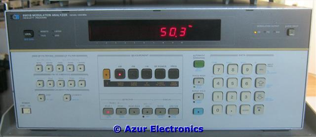
50.3% Amplitude Modulation
Connect a RF Input of 100MHz at 0dBm with 50% AM modulation at 1kHz. Press the AM, AUTOMATIC OPERATION and PEAK+ keys. The Display indicates 50.3% amplitude modulation. This is in automatic tuning mode. Manual tuning is useful if there are multiple signals.
Various detectors are available: PEAK+ or PEAK- checks modulation symetry; both PEAK+ and PEAK- checks the average (PEAK±/2); PEAK+ or PEAK- and PEAK HOLD captures and holds the maximum peak level. AVG checks the rms value of a sinewave. Shift and AVG checks the true rms value.
The AM MODULATION LED is on, indicating that the demodulated signal is available at the rear panel MODULATION OUTPUT connector.
| RF Carrier Frequency | Modulation Rate | Max Depth |
| 150kHz to 9.999MHz | 20Hz to 10kHz | 99% |
| 10MHz to 1300MHz | 20Hz to 100kHz | 99% |
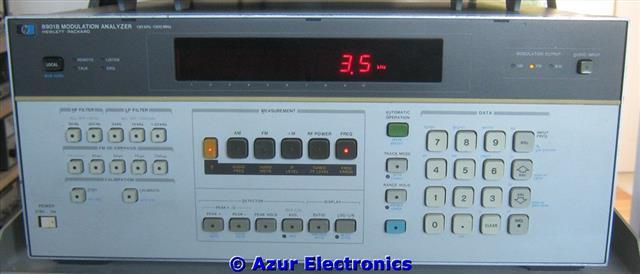
2. FREQUENCY MODULATION
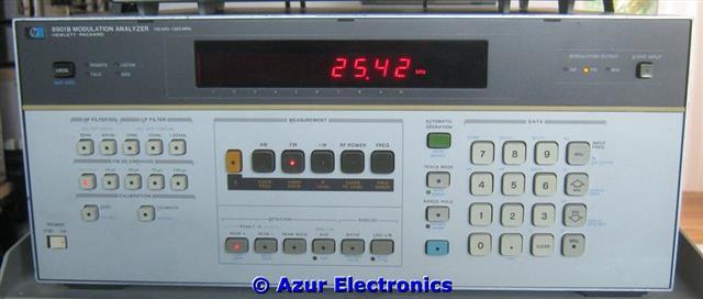
25.42kHz Frequency Deviation
Connect a RF Input of 100MHz at 0dBm with 25kHz FM deviation at 1kHz. Press the FM, AUTOMATIC OPERATION and PEAK+ keys. The Display indicates 25kHz of frequency deviation.
Various detectors for PEAK and AVG are available (as for AM).
4 FM de-emphasis filters are available: 25µs, 50µs, 75µs & 750µs. The PRE DISPLAY key toggles the measurement before and after de-emphasis.
High-pass and low-pass audio filters are available to remove undesirable harmonics, noise, etc from the demodulated signal. The >20kHz is a Bessel filter to minimise overshoot from square-wave modulation such as FSK.
The FM MODULATION LED is on, indicating that the demodulated signal is available at the rear panel MODULATION OUTPUT connector.
| RF Carrier Frequency | Modulation Rate | Max Deviation |
| 150kHz to 9.999MHz | 20Hz to 10kHz | 40kHz peak |
| 10MHz to 1300MHz | 20Hz to 200kHz | 40kHz peak |
3. PHASE MODULATION
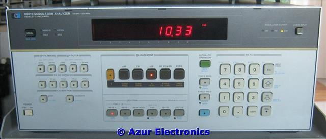
10.33 Radians Phase Deviation
Connect a RF Input of 100MHz at 0dBm with 10 radians phase deviation at 1kHz. Press the фM, AUTOMATIC OPERATION and PEAK+ keys. The Display indicates 10 radians.
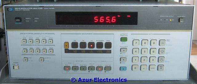
565.6° Phase Deviation
To display the phase deviation in degrees, press 1.745 and RATIO keys. The display indicates 570° approx.
The фM MODULATION LED is on, indicating that the demodulated signal is available at the rear panel MODULATION OUTPUT connector.
The фM MODULATION LED is on, indicating that the demodulated signal is available at the rear panel MODULATION OUTPUT connector.
| RF Carrier Frequency | Modulation Rate |
| 150kHz to 9.999MHz | 200Hz to 10kHz |
| 10MHz to 1300MHz | 200Hz to 20kHz |
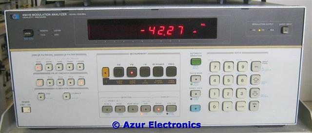
-42dB Residual Modulation, 4 Digit Display
Residual modulation is a measure of the hum and noise of the unmodulated signal. Connect a RF Input of 100MHz at 0dBm with no modulation. Press 50Hz HP FILTER, PRE-DISPLAY, 750µs, FM, blue Shift, RMS, .44, RATIO, LOG/LIN keys. The display indicates hum and noise in dB.
Modulation flatness across the modulation depth (AM) or deviation (FM) can be measured with the RATIO key, for details see page 124 of the HP Operating and Calibration Manual.
Modulation flatness across the modulation depth (AM) or deviation (FM) can be measured with the RATIO key, for details see page 124 of the HP Operating and Calibration Manual.
AUDIO MEASUREMENTS
The frequency of an external audio signal source can be measured as described above in Frequency Measurements.
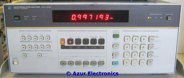
1kHz Frequency, 7 Digit Display
Connect a RF Input of 100MHz at 0dBm with 50% AM modulation at 1kHz. Press the AM and AUTOMATIC OPERATION keys. The Display indicates 50.3% amplitude modulation (as above in Modulation Measurements). Now press the gold S and AUDIO FREQ keys and the display indicates the frequency of the demodulated audio signal, in this case 1kHz. The true RMS detector is used to make this measurement.
| Audio Frequency | Max External Input Voltage |
|
20Hz to 250kHz (usable to 600kHz) |
3Vrms |
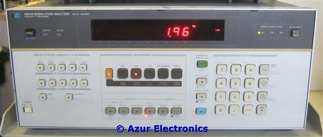
2% Audio Distortion, 3 Digit Display
Audio distortion can also be measured at 400Hz or 1kHz for an external audio signal source or demodulated audio. For 1kHz, press the gold S and AUDIO DISTN keys. The display indicates the percentage distortion of the 1kHz audio signal. For 400Hz, press the blue S and 400Hz DISTN keys. The display indicates the percentage distortion of the 400Hz audio signal.
| Audio Frequency |
Max External Input Voltage |
Display Range |
| 400Hz & 1kHz | 3Vrms |
0.01% (-80dB) to 100.0% (0.00dB) |
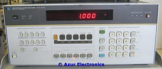
1Vrms Audio Level, 4 Digit Display
Audio level measurements can be made on an external audio signal source (but not demodulated audio). Press the 30.0 SPCL key. The display indicates the rms voltage level of the audio signal. Press the blue S and µV or mV or Volts keys to select the desired units.
| Audio Frequency |
Input Voltage |
| 50Hz to 40kHz | 100mV to 3V |
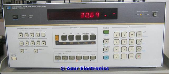
30dB SINAD, 4 Digit Display
SINAD (Signal to Noise And Distortion Ratio) is a measure of the quality of a signal. Connect a RF Input of 100MHz at 0dBm with 50% AM (or FM) modulation at 1kHz. Press AM, 29.0 SPCL, 1kHz DISTN, LOG/LIN (and Filters if required) keys. The display indicates the SINAD Ratio in dB's.
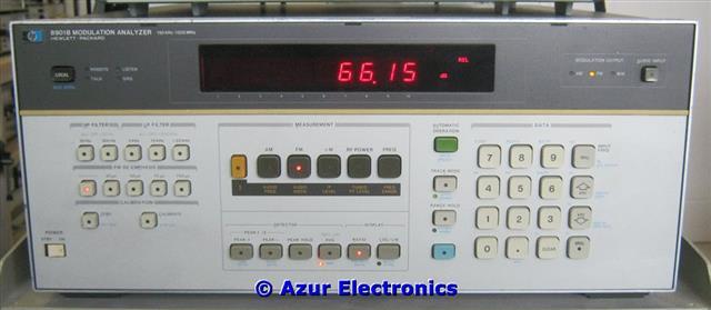
66dB Signal to Noise, 4 Digit Display
Signal to Noise on AM, or hum and noise, on FM signals. Connect a RF Input of 100MHz at 0dBm with no modulation. Press AM or FM, blue shift, RMS, RATIO, LOG/LIN keys. Turn on modulation (FM in this case) and display indicates signal to noise ratio in dB's.
SPECIAL FUNCTIONS
The SPCL (Special Functions) key allows you to override the automatic settings.
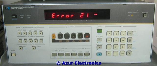
Error Display
Pressing an inappropriate key, such as CALIBRATE will display an error code.
A list of error codes is on pages 97-98, 107-108 & 114-116 of the HP Operating and Calibration Manual.
A list of error codes is on pages 97-98, 107-108 & 114-116 of the HP Operating and Calibration Manual.