
Welcome to
Azur Electronics
Azur Electronics
OPERATING LECROY 9310
DUAL 300MHz OSCILLOSCOPE
DUAL 300MHz OSCILLOSCOPE
Home
Projects
Test Equipment
- Accessories
- Adaptors
- Amplifiers
- Attenuators
- Cables
- Frequency Counters
- Logic Analysers
- Multi-Meters
- Network Analysers
- Oscilloscopes
- Power Meters
- Power Supplies
- Prototyping Equipment
- Signal Generators
- Spectrum Analysers
- Tools
Operating Information
- Operating HP 141T
- Operating HP 1630D
- Operating HP 8175A
- Operating HP 8407A
- Operating HP 8410C
- Operating HP 8552B IF Section
- Operating HP 8553B RF Section
- Operating HP 8554B RF Section
- Operating HP 8555A RF Section
- Operating HP 8556A LF Section
- Operating HP 8594E Spectrum Analyser
- Operating HP 8901B
- Operating LeCroy 9310
Technical
- Allen Key Sizes
- High Voltage Measurement
- HP Cases
- HP Information
- HP-IB Interface Bus
- Measurement Units
- Motorola ECL
- RF Connectors
- RF Power - Voltage Conversion
For Sale
Wanted
Links
About Me
Contact Me
Site Map
December 2011
The LeCroy 9310 Dual 300MHz Oscilloscope is a powerful and complicated Digital Storage Oscilloscope, with both basic and advanced facilities, including FFT for spectrum analysis. Most of my test equipment is fairly easy to use and I have had previous experience with similar items and their applications. These are my working notes.
The LeCroy 9310 Dual 300MHz Oscilloscope is a powerful and complicated Digital Storage Oscilloscope, with both basic and advanced facilities, including FFT for spectrum analysis. Most of my test equipment is fairly easy to use and I have had previous experience with similar items and their applications. These are my working notes.
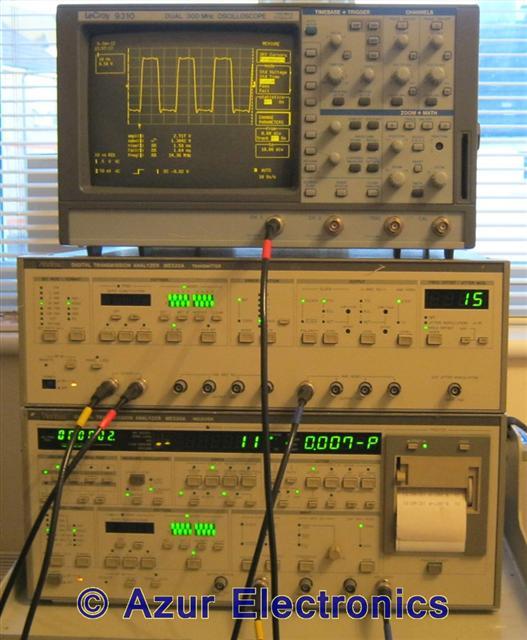
Testing Anritsu ME520A with LeCroy 9310
September 2019
With power on, the 9310 runs self-tests followed by a full system calibration. This takes <15s.
With power on, the 9310 runs self-tests followed by a full system calibration. This takes <15s.
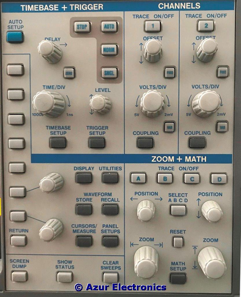
Control Panel
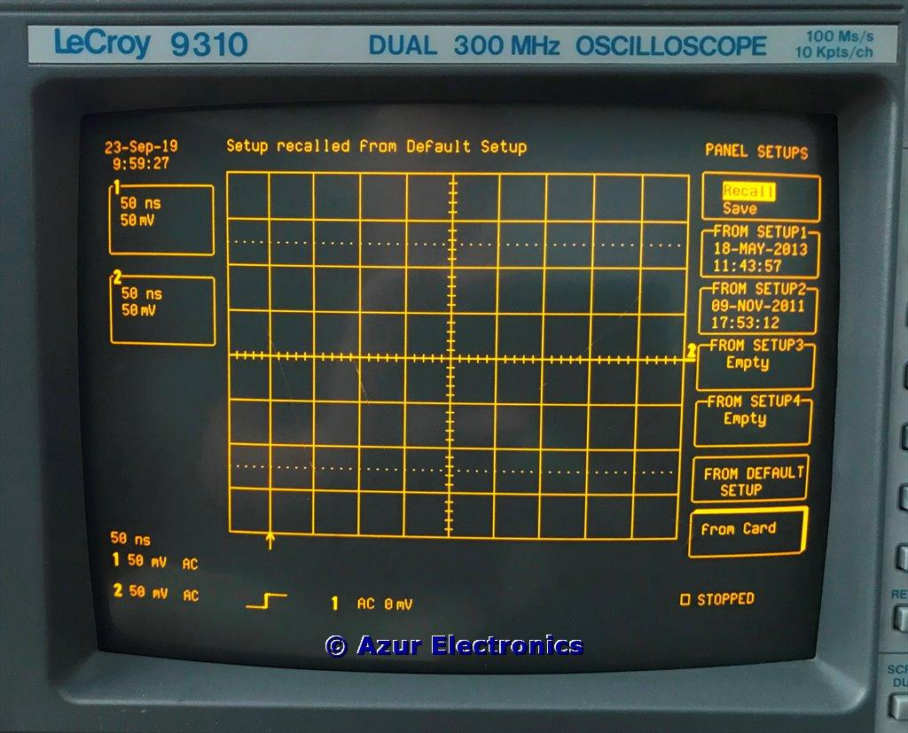
Initialise
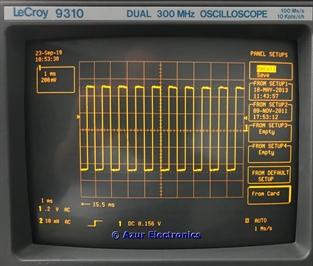
Initialise by pressing PANEL SETUPS, then top menu button select RECALL, then select FROM DEFAULT SETUP.
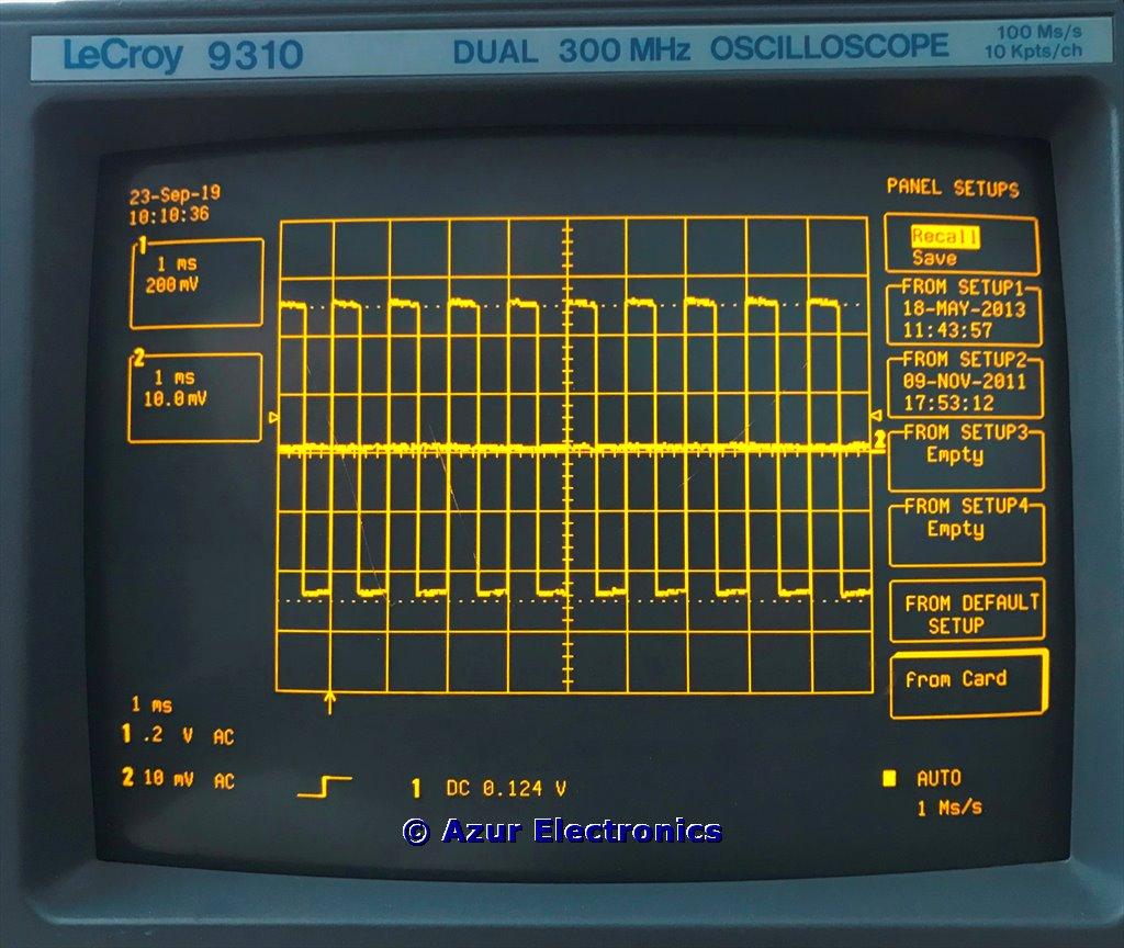
Auto Setup
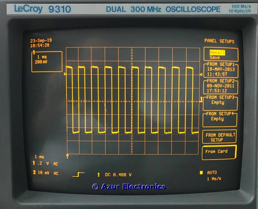
Connect a BNC cable from CAL output (1Vpp 1kHz) to CH 1 input. Press AUTO SETUP to set optimum trigger level, timebase and vertical settings to display the input signal. Ch 1 - 1kHz square wave 1ms/div 200mV/div. Ch 2 - no signal
Ch 1 On, Ch 2 Off
Turn off Ch 2 by pressing TRACE ON / OFF 2 button.
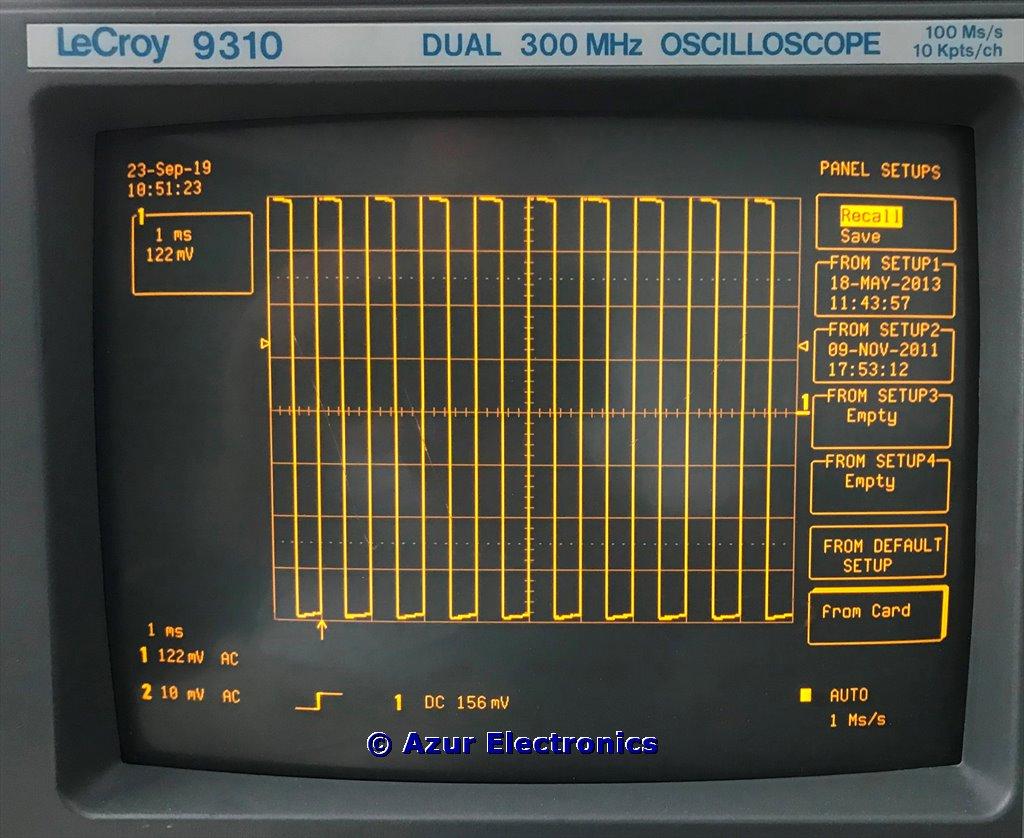
Variable Vertical Gain 122mV/div
VOLTS/DIV knob provides 2mV to 5V per division in a 1, 2, 5 sequence.
VAR button allows fine tuning the vertical gain. Filling the grid from top to bottom ensures that the signal uses the full range of digitising levels available (8 bits = 256 levels) for the best vertical resolution. Press VAR again to return to normal.
VAR button allows fine tuning the vertical gain. Filling the grid from top to bottom ensures that the signal uses the full range of digitising levels available (8 bits = 256 levels) for the best vertical resolution. Press VAR again to return to normal.
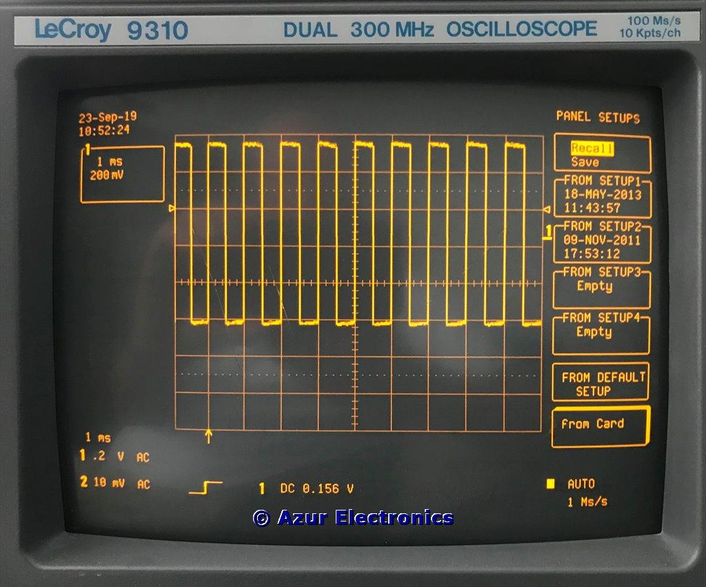
Offset Vertical Position
OFFSET button adjusts the vertical position of the signal. The "1" label on the right hand side of the grid indicates the ground level of Ch 1. Similarly the "2" label indicates the ground level of Ch 2. Press OFFSET again to return to normal.
Pre and Post Trigger Delay
Trigger DELAY knob adjusts the trigger's horizontal position from 0% to 100% pre-trigger from left to right edge of the grid. The pre-trigger position is indicated by the "upward arrow" at the bottom of the grid. DELAY can also be used for post-trigger in seconds up to 10K divisions and is indicated at the bottom of the grid. Press ZERO to return to normal.
Trigger Level
Trigger LEVEL knob adjusts the trigger's vertical threshold. The threshold position is indicated by the "left and right arrows" each side of the grid. This only applies if the trigger source is Ch 1 or 2.
Zoom
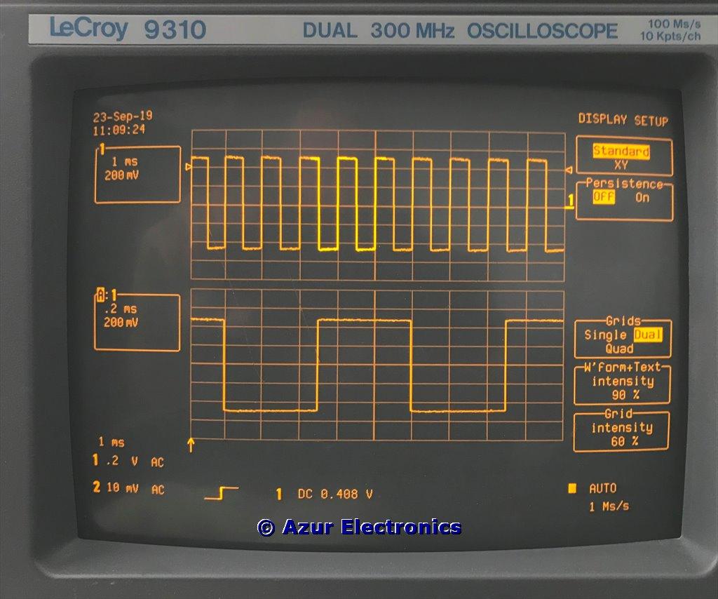
To Zoom, press DISPLAY, then on Grids menu select DUAL. Press A to turn on Trace A. Turn vertical POSITION to move Trace A to the lower grid. Turn horizontal ZOOM to adjust the expansion factor of Trace A. Turn horizontal POSITION to move the magnified part of Trace 1. Turn vertical ZOOM to magnify Trace A vertically. RESET button returns zomm and position settings to normal.
Measure Cursors: Time & Absolute
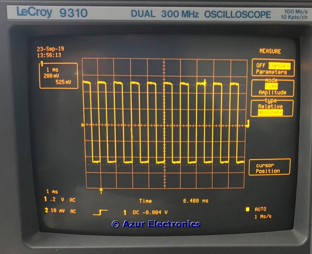
Select Cursors on the MEASURE menu. Then select Time and Absolute. Adjust Cursor position to move the cross-hair to the deired point on the waveform. Its time from the trigger point is shown at the bottom of the grid and its voltage is shown in the box at the top left of the grid.
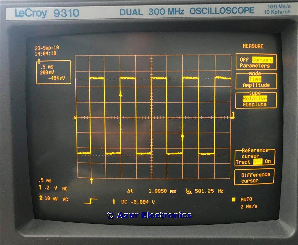
Measure Cursors: Time & Relative
Change the type to Relative and 2 cursor arrows are available. Both cursor position knobs can be used to select the desired part of the waveform. The relative time and voltage between them is displayed.
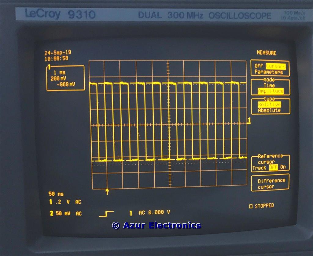
Measure Cursors: Amplitude & Relative
Select Amplitude and Absolute and a horizontal cursor line indicates voltage from ground 0V. Select Relative and 2 horizontal cursor lines indicate voltage between cursors.
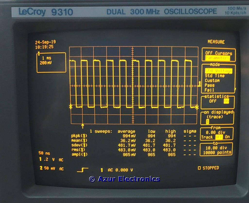
Parameters: Std Voltage
Select Parameters on the MEASURE menu. Then select Std Voltage. Display provides measurements of peak to peak, mean, standard deviation, rms, amplitude voltages. Selecting statistics On provides averages of lowest and highest values and standard deviation.
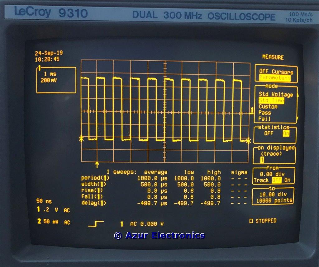
Parameters: Std Time
Select Std Time. Display provides measurements of period, width, rise, fall, delay times. Selecting statistics On provides averages of lowest and highest values and standard deviation.
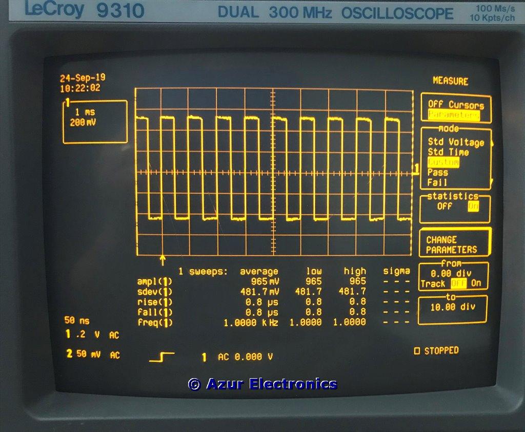
Custom Parameters
Select Custom and other parameters are measured including frequency. These can be further customised by pressing CHANGE PARAMETERS. Press RETURN to go back to the MEASURE menu. Pass and Fail settings can also be specified.
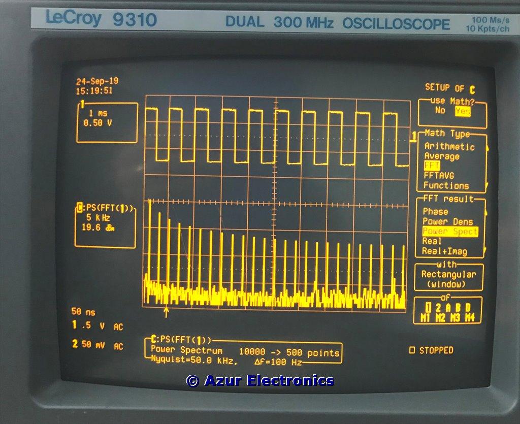
FFT Spectrum Analysis
Fast Fourier Transform (FFT) of a signal visualises it in the frequency domain.
Press MATH SETUP, TRACE ON / OFF C, use Math? Yes, Math Type FFT, FFT result Power Spect. Use POSITION and ZOOM controls to place CAL signal in the top half of the grid and the Trace C FFT signal at 5kHz/div in the bottom half of the grid. The FFT signal shows the fundamental at 1kHz and the harmonics at 3kHz, 5kHz, 7kHz, etc.
Press MATH SETUP, TRACE ON / OFF C, use Math? Yes, Math Type FFT, FFT result Power Spect. Use POSITION and ZOOM controls to place CAL signal in the top half of the grid and the Trace C FFT signal at 5kHz/div in the bottom half of the grid. The FFT signal shows the fundamental at 1kHz and the harmonics at 3kHz, 5kHz, 7kHz, etc.
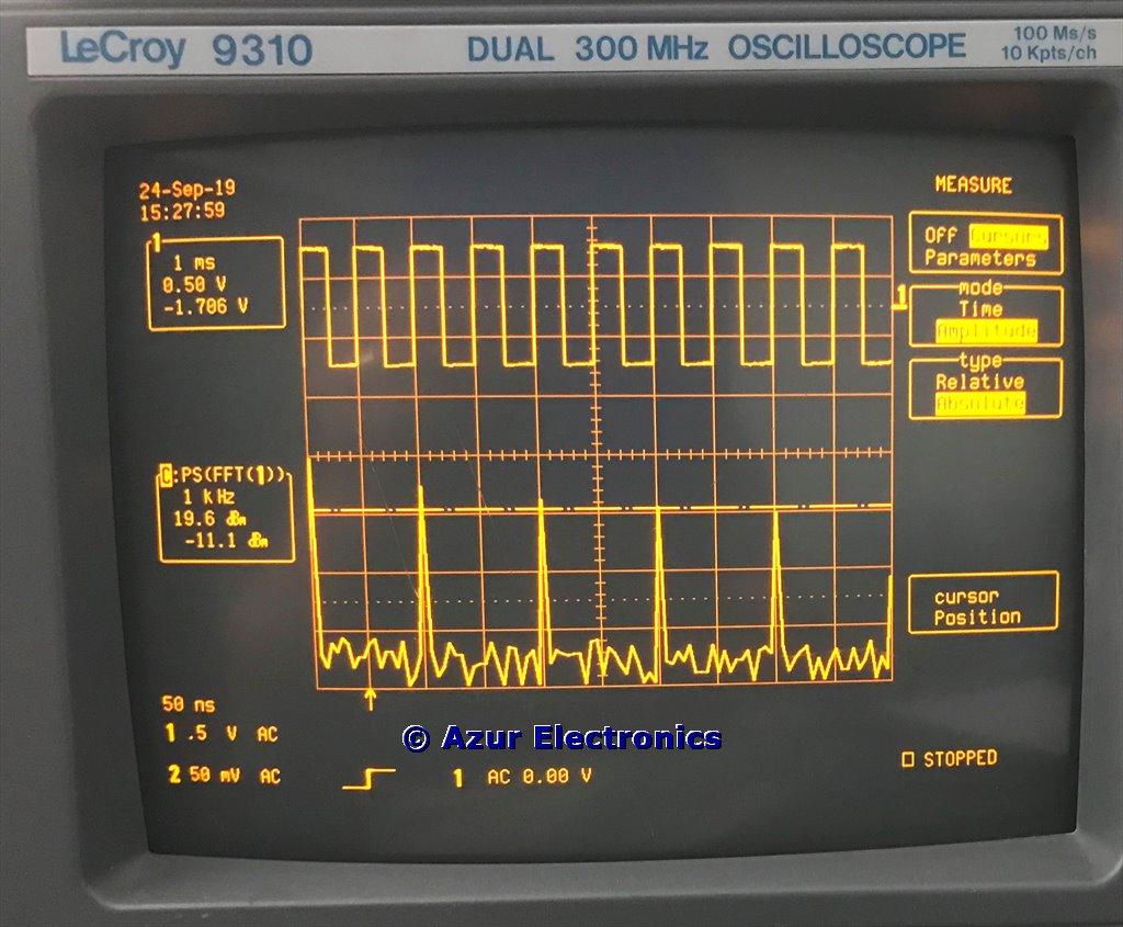
FFT Spectrum Analysis
Press CURSORS / MEASURE button, select Cursors, Amplitude, Absolute. Zoom to 1kHz/div. Cursor measures FFT signal in dB. In this example 3rd harmonic at 7kHz -11.1dB.
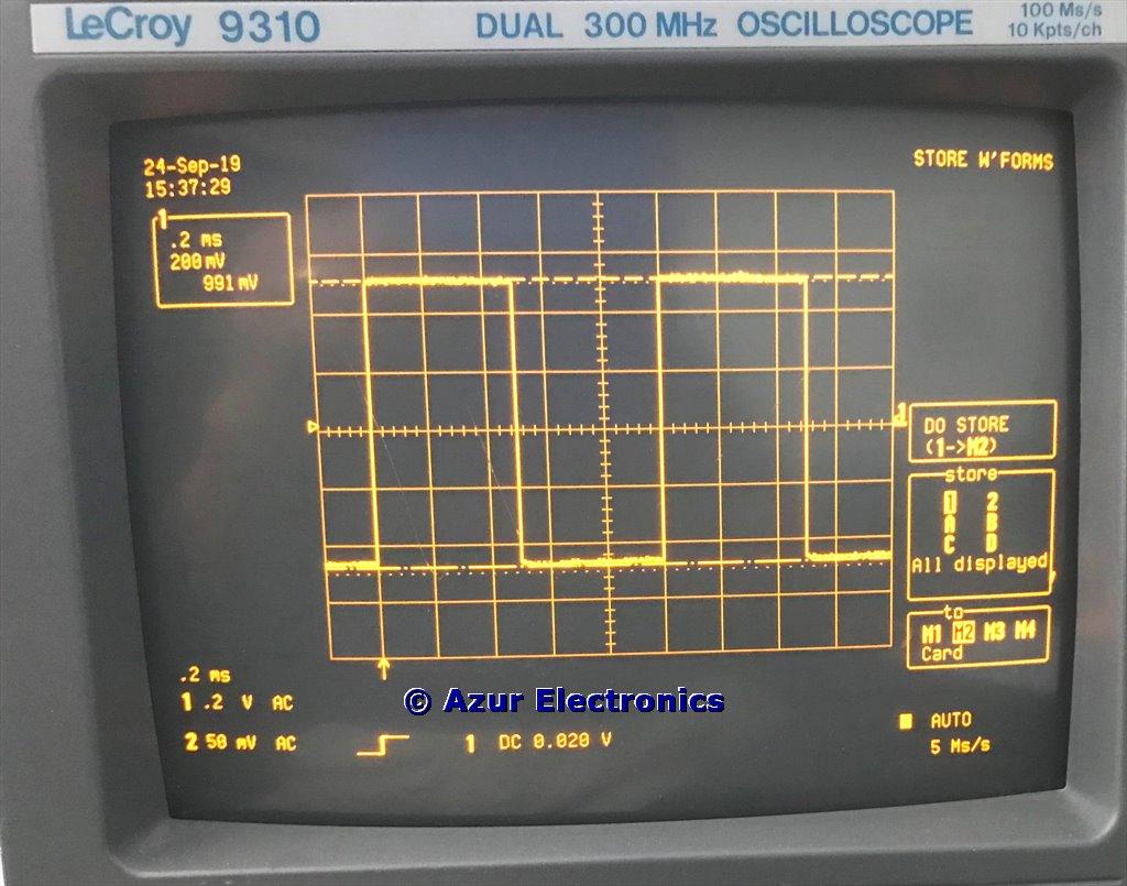
Store Waveforms
There are 4 waveform memories. Press WAVEFORM STORE, select required trace 1, 2, A, B, C or D from store menu. Select required memory M1, M2, M3 or M4 from to menu. Select DO STORE to save.
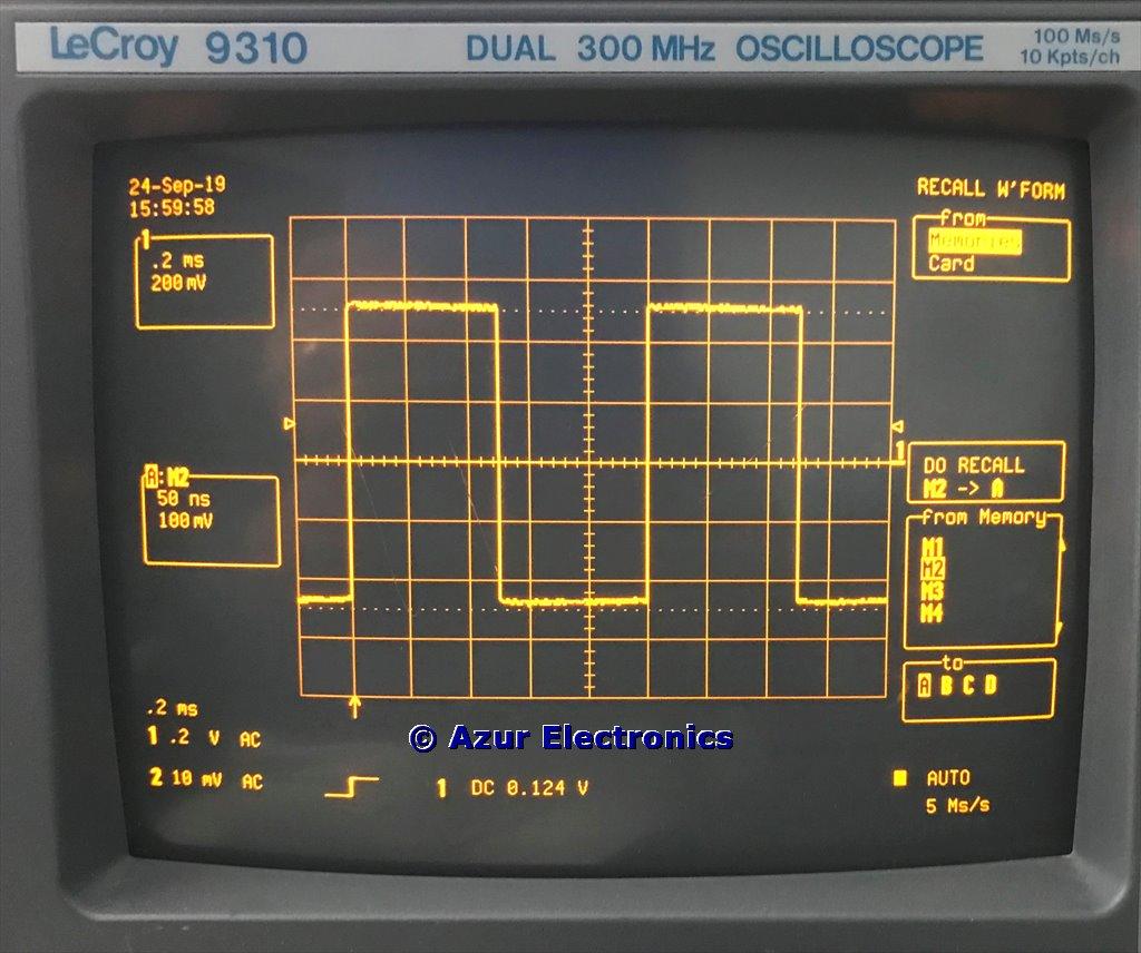
Recall Waveforms
To recall a stored waveform memories press WAVEFORM RECALL, select required memory M1, M2, M3 or M4 from the from menu. Select required trace A, B, C or D from to menu. Select Select DO RECALL to recall.
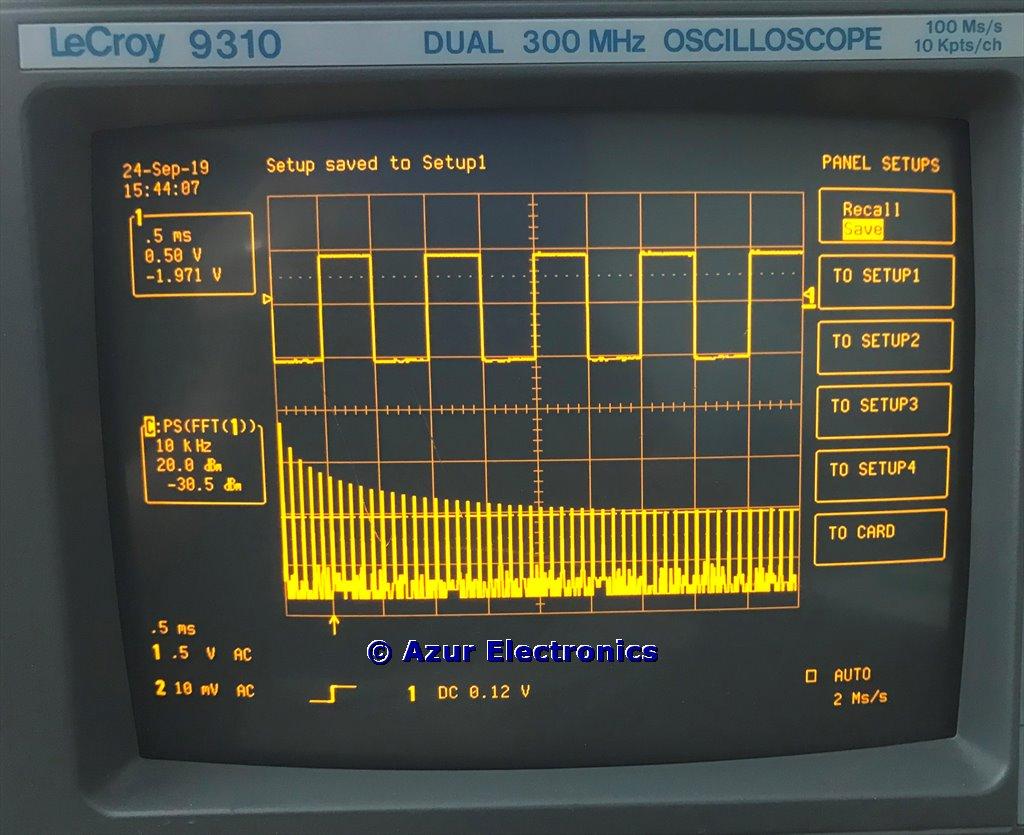
Store Panel Setup
Complete panel setups can also be stored. Press PANEL SETUPS, select Save from menu, select required TO SETUP 1, 2, 3 or 4 to save.
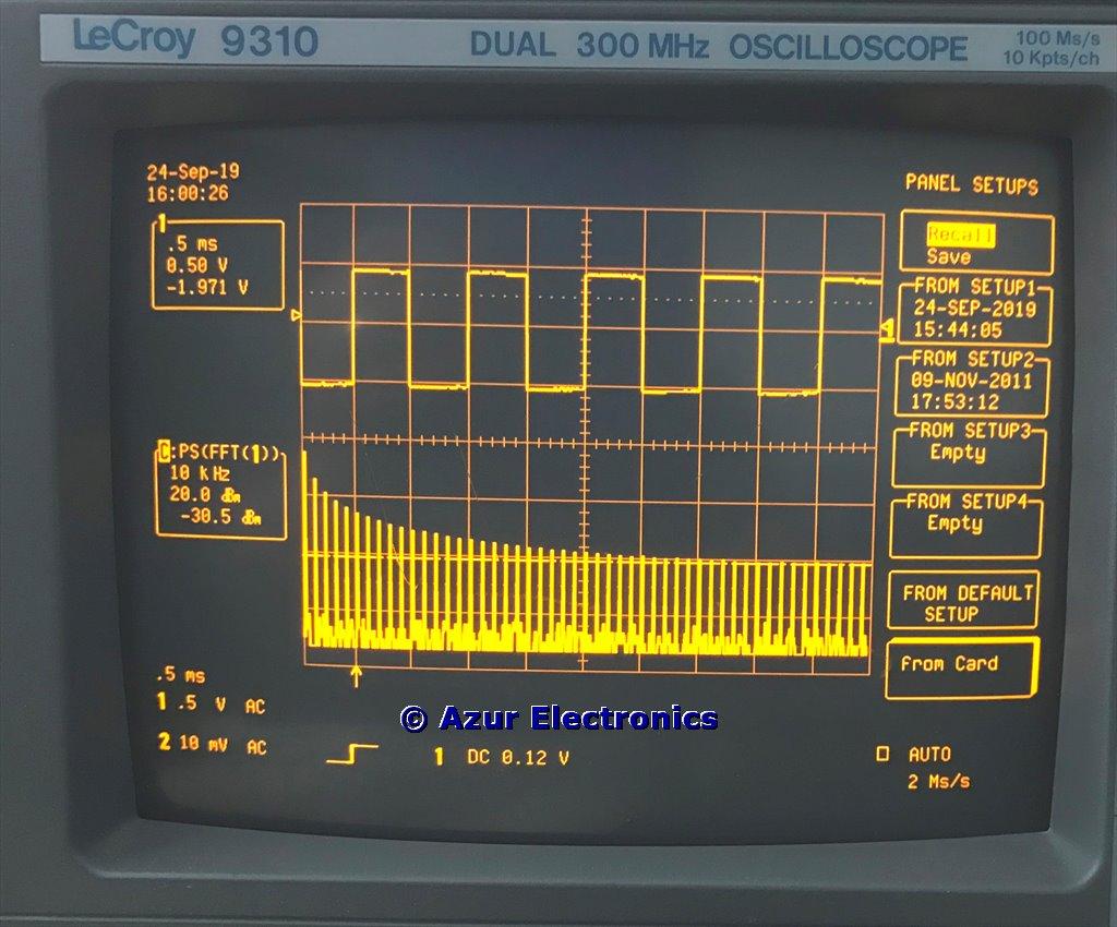
Recall Panel Setup
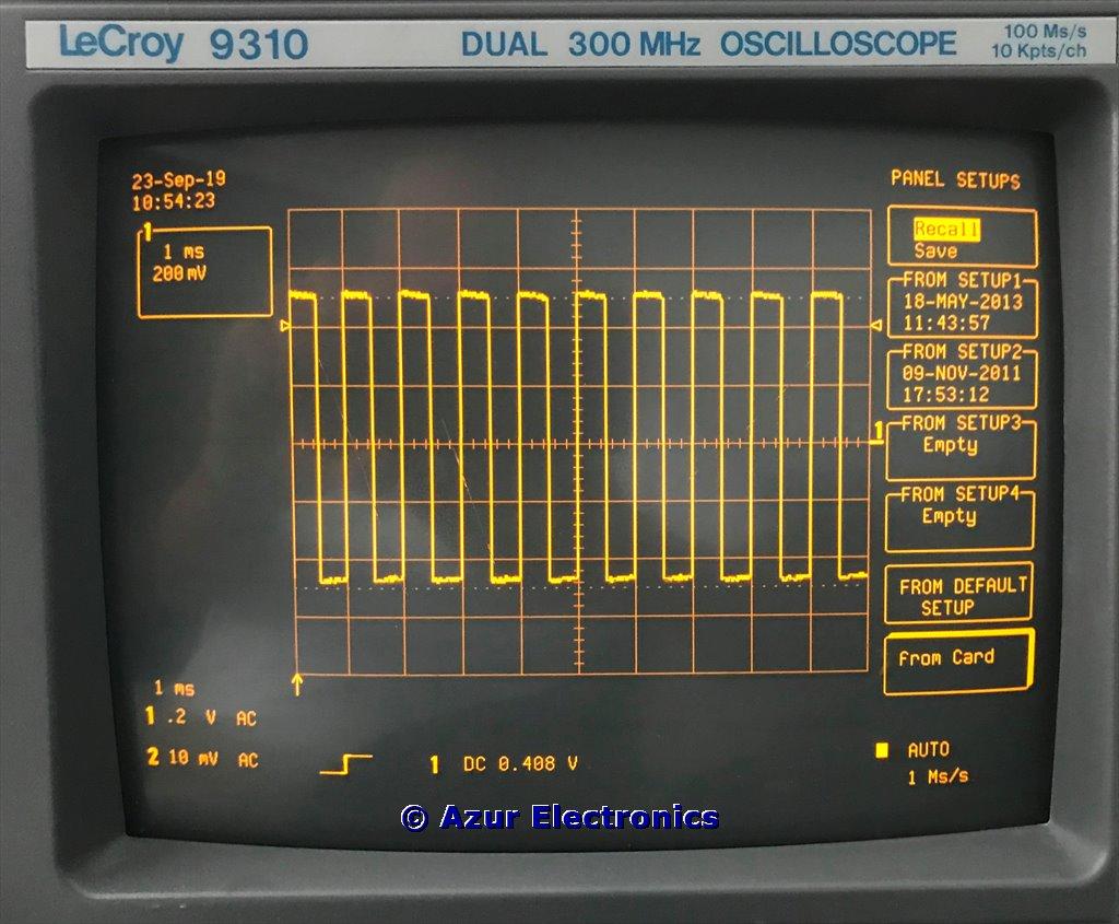
To recall panel setups press PANEL SETUPS, select Recall from menu, select required FROM SETUP 1, 2, 3 or 4 to recall.
This Operating Information only covers the basics. To get the best out of this very powerful digital storage oscilloscope it is essential to read the Operators Manual (258 pages) and the Hands-On Guide (208 pages)!