
Welcome to
Azur Electronics
Azur Electronics
Home
Projects
Test Equipment
- Accessories
- Adaptors
- Amplifiers
- Attenuators
- Cables
- Frequency Counters
- Logic Analysers
- Multi-Meters
- Network Analysers
- Oscilloscopes
- Power Meters
- Power Supplies
- Prototyping Equipment
- Signal Generators
- Spectrum Analysers
- Tools
Operating Information
- Operating HP 141T
- Operating HP 1630D
- Operating HP 8175A
- Operating HP 8407A
- Operating HP 8410C
- Operating HP 8552B IF Section
- Operating HP 8553B RF Section
- Operating HP 8554B RF Section
- Operating HP 8555A RF Section
- Operating HP 8556A LF Section
- Operating HP 8594E Spectrum Analyser
- Operating HP 8901B
- Operating LeCroy 9310
Technical
- Allen Key Sizes
- High Voltage Measurement
- HP Cases
- HP Information
- HP-IB Interface Bus
- Measurement Units
- Motorola ECL
- RF Connectors
- RF Power - Voltage Conversion
For Sale
Wanted
Links
About Me
Contact Me
Site Map
OPERATING HP 1630D
LOGIC ANALYSER
LOGIC ANALYSER
July 2010
Understanding the HP 1630D Logic Analyser is my first attempt at using logic analysis. Most of my test equipment is fairly easy to use and I have had previous experience with similar items and their applications. Logic Analysers are one (of the many) areas where I have little knowledge, although I appreciate their general function, so these are my working notes.
Understanding the HP 1630D Logic Analyser is my first attempt at using logic analysis. Most of my test equipment is fairly easy to use and I have had previous experience with similar items and their applications. Logic Analysers are one (of the many) areas where I have little knowledge, although I appreciate their general function, so these are my working notes.
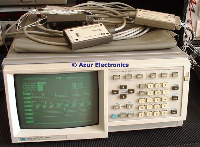
HP 1630D front view with Pods & cables
This HP 1630D Logic Analyser was manufactured circa 1983 and by today's standards is probably totally obsolete, even though it cost $10,630 in 1986. For my puposes it is an excellent learning tool even if it is 30 years old! For more information on the Logic Analyser, see HP 1630D Logic Analyser.
The Operating and Programming Manual of October 1985 is very comprehensive although the illustrations are indistinct. This has prompted me to work through the Manual and take new photos where necessary. Hopefully at the end of this lengthy process I will have a lot more expertise, plus I can determine if the 1630D and/or 1630G will be all that I need for my design work.
The Operating and Programming Manual of October 1985 is very comprehensive although the illustrations are indistinct. This has prompted me to work through the Manual and take new photos where necessary. Hopefully at the end of this lengthy process I will have a lot more expertise, plus I can determine if the 1630D and/or 1630G will be all that I need for my design work.
Operating and Programming Manual
Chapter 1 General Information
Chapter 2 Installation
Chapter 3 Front Panel Controls And Menu Map
Chapter 4 State Measurements
Chapter 5 Performance Analysis Measurements
Chapter 6 Timing Measurements
Chapter 7 Interactive State And Timing Measurements
Chapter 8 The Peripherals Menu
Chapter 9 Using HP-IB Or HP-IL Interface
Appendix A Display Messages
Appendix B An HP-IB Overview
Appendix C Using A Printer
Appendix D Using The Disc Memory Accessory
Appendix E Using The Tape Memory Accessory
My notes will be an overview in some cases and a lot more detailed in others by using a secondary webpage with instructions and screen shots. Also I'm not working through the Manual in any strict order as timing measurements is my first area of interest.
[With acknowledgement and thanks to HP for reproducing some text from their Manual].
Chapter 1 General Information
Introduction, description and specification of the 1630A, D & G Logic Analysers. The 1630G has the added feature of an internal storage space which allows the user to store menu configurations and an inverse assembler, which can be loaded at power-up. System, format, trace, list, waveform, and chart displays are described. The 1630A provides 35 channels for state, timing, and combined state/timing measurements. The 1630D provides 8 additional channels for timing measurements. The 1630G provides 30 additional channels for state measurements.
Chapter 2 Installation
Power-up, self-test and probe connection information.
Chapter 3 Front Panel Controls And Menu Map
Function of all front panel keys and map of menu commands.
Chapter 4 State Measurements
Features:
The 1630D provides 43 state channels and the 1630G 65 state channels.
The Analyser is capable of capturing large quantities of data. To make this data useful, the incoming data needs to be formatted in an arrangement that is easily comprehensible. This is accomplished by grouping the incoming lines and labeling the groups for the typical connections for the address, data, status, and other lines of interest. Incoming data may be further identified by assigning user defined labels for conditions rather than the provided bases for hexidecimal, binary, or ASCII. Another type of user base may be assigned in which relocatable code is labeled by the user.
The next step in making the captured data useful is to edit the data before it is stored by the analyser. Selective tracing techniques are used for recognizing and storing only qualified data. The Logic Analyser provides a trace specification menu in which resource terms may be identified for selective tracing. Resource terms may be specified for simple triggering, sequence triggering, sequence restart, and store qualifying.
For detailed instructions and screen shots, see Operating HP 1630D State Measurements.
Chapter 5 Performance Analysis Measurements
Chapter 6 Timing Measurements
Features:
The 1630D provides 16 timing channels and the 1630G 8 timing channels.
Timing analysis is directed toward timing relationships between I/O signals or control lines, and propagation delays between or across logic gates. Samples of data are taken, asynchronously, on every pulse of a clock internal to the analyser. The analyser determines whether the data is less or greater than a prespecified threshold voltage level and displays the result as either logic 1 or 0. The display stays the same level until the next sample is taken.
Glitches are handled by a glitch detection circuit which is independent of the sampling rate. Dual detectors are on an alternate sample period with a slight overlap. Each detector looks for 2 threshold crossings, identifying a glitch. If a glitch is found, it is stored in a memory separate from the timing data. When glitch detection is on, the assigned timing channels are halved.
Trigger detection is accomplished by a method independent of the sampling clock. To eliminate false triggering, the analyser has a filter which is used when specifying trigger duration. Trigger pattern duration is selectable from 20ns to 1ms to qualify the trigger on a time basis. Edge triggering is available on 4 channels per Pod assigned to timing measurements. It is used where a pattern may not be adequate for triggering or may be used to qualify a pattern. With edge detection, triggering can take place on an edge that doesn't show up in the trace (glitch triggering). When the analyser finds the trigger, the tracepoint is positioned as specified in the specification menu (at start, centre, or end of trace). The trace specification tells the analyser when to stop the measurement. Enough information is captured after the trigger to place it properly in trace memory. Usually timing measurements are taken with the trigger in centre trace position. The tracepoint may be delayed up to 9999 seconds after the trigger.
For detailed instructions and screen shots, see Operating HP 1630D Timing Measurements.
Chapter 7 Interactive State And Timing Measurements
Chapter 8 The Peripherals Menu
[With acknowledgement and thanks to HP for reproducing some text from their Manual].
Chapter 1 General Information
Introduction, description and specification of the 1630A, D & G Logic Analysers. The 1630G has the added feature of an internal storage space which allows the user to store menu configurations and an inverse assembler, which can be loaded at power-up. System, format, trace, list, waveform, and chart displays are described. The 1630A provides 35 channels for state, timing, and combined state/timing measurements. The 1630D provides 8 additional channels for timing measurements. The 1630G provides 30 additional channels for state measurements.
Chapter 2 Installation
Power-up, self-test and probe connection information.
Chapter 3 Front Panel Controls And Menu Map
Function of all front panel keys and map of menu commands.
Chapter 4 State Measurements
Features:
• Continuous trace until compare "equal to" or "not equal to" is provided. The compare file is the width of the analyser, and has a depth of up to 16 words with the 1630A/D and in the edit compare mode of the 1630G. The 1630G has a full compare mode in which the entire trace may be compared.
• Three ORed clocks given in single-phase or two-phase demultiplexing modes.
• Data sampling up to 25MHz.
• 1024 states available in memory after a trace.
• A State Chart of any user-defined label may be selected for display.
• State analysis can be armed by the timing analysis section.
• A State Histogram of any user-defined label may be selected.
• A Time Interval Histogram of the time software takes to execute from one selected point in software to another.
• Time positional measurements for the occurrences of an event per unit time may be made (1630G only).
• Linkage measurements which show the relative frequency of occurrence of a set of events (1630G only).
The 1630D provides 43 state channels and the 1630G 65 state channels.
The Analyser is capable of capturing large quantities of data. To make this data useful, the incoming data needs to be formatted in an arrangement that is easily comprehensible. This is accomplished by grouping the incoming lines and labeling the groups for the typical connections for the address, data, status, and other lines of interest. Incoming data may be further identified by assigning user defined labels for conditions rather than the provided bases for hexidecimal, binary, or ASCII. Another type of user base may be assigned in which relocatable code is labeled by the user.
The next step in making the captured data useful is to edit the data before it is stored by the analyser. Selective tracing techniques are used for recognizing and storing only qualified data. The Logic Analyser provides a trace specification menu in which resource terms may be identified for selective tracing. Resource terms may be specified for simple triggering, sequence triggering, sequence restart, and store qualifying.
For detailed instructions and screen shots, see Operating HP 1630D State Measurements.
Chapter 5 Performance Analysis Measurements
Chapter 6 Timing Measurements
Features:
• Sampling ranges from 10ns to 500ms, in increments of 1, 2 & 5.
• Timing waveforms that can be magnified from X1 to X40, in 1, 2 & 4 increments.
• Time between dual cursors (x & o) can be displayed to within 1 sample period.
• 1024 samples available in memory after a trace.
• Timing analysis can be armed by the state analysis section.
• Timing can be triggered by an asynchronous pattern, ANDed with a glitch or edge on any channel, and patterns that exceed or fall short of a specified time limit.
The 1630D provides 16 timing channels and the 1630G 8 timing channels.
Timing analysis is directed toward timing relationships between I/O signals or control lines, and propagation delays between or across logic gates. Samples of data are taken, asynchronously, on every pulse of a clock internal to the analyser. The analyser determines whether the data is less or greater than a prespecified threshold voltage level and displays the result as either logic 1 or 0. The display stays the same level until the next sample is taken.
Glitches are handled by a glitch detection circuit which is independent of the sampling rate. Dual detectors are on an alternate sample period with a slight overlap. Each detector looks for 2 threshold crossings, identifying a glitch. If a glitch is found, it is stored in a memory separate from the timing data. When glitch detection is on, the assigned timing channels are halved.
Trigger detection is accomplished by a method independent of the sampling clock. To eliminate false triggering, the analyser has a filter which is used when specifying trigger duration. Trigger pattern duration is selectable from 20ns to 1ms to qualify the trigger on a time basis. Edge triggering is available on 4 channels per Pod assigned to timing measurements. It is used where a pattern may not be adequate for triggering or may be used to qualify a pattern. With edge detection, triggering can take place on an edge that doesn't show up in the trace (glitch triggering). When the analyser finds the trigger, the tracepoint is positioned as specified in the specification menu (at start, centre, or end of trace). The trace specification tells the analyser when to stop the measurement. Enough information is captured after the trigger to place it properly in trace memory. Usually timing measurements are taken with the trigger in centre trace position. The tracepoint may be delayed up to 9999 seconds after the trigger.
For detailed instructions and screen shots, see Operating HP 1630D Timing Measurements.
Chapter 7 Interactive State And Timing Measurements
Chapter 8 The Peripherals Menu
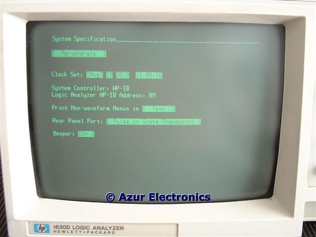
Peripherals Menu
Pressing SYSTEM then NEXT will give the Peripherals Menu. From this Menu you can: set the clock date and time; confirm HP-IB address of the Analyser; set printing in text (ASCII) or graphics (HP Graphics codes); select the desired ouput to the rear panel BNC port; and set the internal beeper on or off.
Chapter 9 Using HP-IB Or HP-IL Interface
Contains the programming instructions. The 1630A/D uses HP-IL mass storage and the 1630G uses HP-IB mass storage. The HP-IB Interface Bus (also known as GP-IB and IEEE-488) superceded the HP-IL Interface Loop. These both allowed a number of items to connect to the bus as controllers and/or peripherals. See HP-IB Interface Bus for details.
Appendix A Display Messages
This lists and defines each of the status, error and prompt messages that appear on the screen.
Appendix B An HP-IB Overview
Defines terms and concepts used to describe HP-IB system operations.
Appendix C Using A Printer
Instructions on how to connect the Analyser via HP-IB to a graphics printer (such as HP 2671G) to print copies of Analyser displays and contents of its memory. Although this printer is obsolete, there must be modern HP-IB printers or printer controllers available.
Appendix D Using The Disc Memory Accessory
Instructions on how to connect the Analyser via HP-IB to a floppy disc drive (such as HP 9121D/S) to store and load test setups and captured data. The floppy disc drive is now obsolete, but there probably is a means of using modern memory storage.
Appendix E Using The Tape Memory Accessory
Instructions on how to connect the Analyser via HP-IL to a digital cassette tape drive (such as HP 82161A) to store and load test setups and captured data. The cassette tape and HP-IL are now obsolete, so there is unlikely to be any use for this interface.