Welcome to
Azur Electronics
Azur Electronics
Home
Projects
Test Equipment
- Accessories
- Adaptors
- Amplifiers
- Attenuators
- Cables
- Frequency Counters
- Logic Analysers
- Multi-Meters
- Network Analysers
- Oscilloscopes
- Power Meters
- Power Supplies
- Prototyping Equipment
- Signal Generators
- Spectrum Analysers
- Tools
Operating Information
- Operating HP 141T
- Operating HP 1630D
- Operating HP 8175A
- Operating HP 8407A
- Operating HP 8410C
- Operating HP 8552B IF Section
- Operating HP 8553B RF Section
- Operating HP 8554B RF Section
- Operating HP 8555A RF Section
- Operating HP 8556A LF Section
- Operating HP 8594E Spectrum Analyser
- Operating HP 8901B
- Operating LeCroy 9310
Technical
- Allen Key Sizes
- High Voltage Measurement
- HP Cases
- HP Information
- HP-IB Interface Bus
- Measurement Units
- Motorola ECL
- RF Connectors
- RF Power - Voltage Conversion
For Sale
Wanted
Links
About Me
Contact Me
Site Map
REPAIR HP 180A OSCILLOSCOPE
September 2019
The HP 180A Oscilloscope on initial testing indicated a fault with the triggering not operational and Channel B Attenuator is intermittant.
Cleaning all the switches with switch cleaner solved the intermittancy.
The HP 1821A is located at the bottom right hand side of the case. The side cover is easy to remove as it is just held on with 2 latches. Access to the pcb is a bit restricted. There is a HP 10407A Plug-In Extender, but I don't have it, probably very rare.
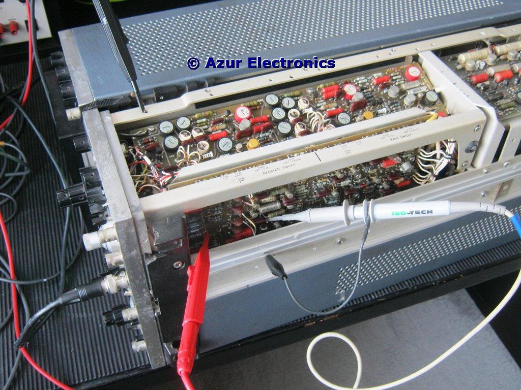
Testing the Triggering PCB
Checked the +100V, -100V, +15V and -12.6V power supplies first and all ok.
Checking through the circuit with an external trigger source connected showed that the trigger comparator Q104 & Q105 was not switching the tunnel diode CR106. Fortunately Q105 was faulty (a 2N3904 NPN) rather than the tunnel diode and was replaced. The 2 Plug-In units are easy to extract from the 180A Mainframe, although soldering has to be done from the component side.
Tested the triggering and now working correctly.
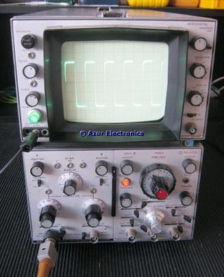
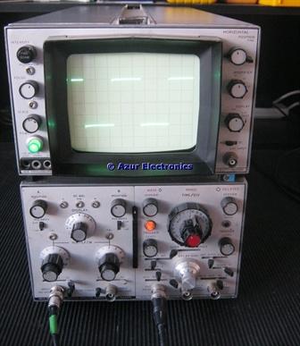
Calibrate signal, normal sweep, internal triggered, +ve slope, dc coupled,
main (left) and mixed (right) displays
main (left) and mixed (right) displays
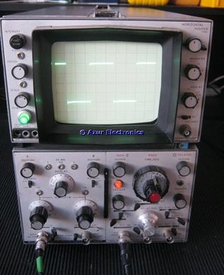
External signal, normal sweep, external triggered,
+ve slope (left), -ve slope (right), dc coupled, displays
+ve slope (left), -ve slope (right), dc coupled, displays
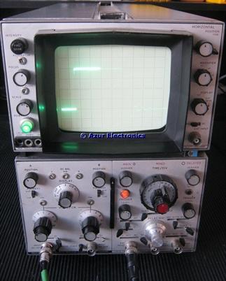
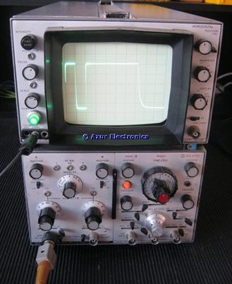
External signal, normal sweep, external triggered,
+ve slope, dc coupled, mixed timebase (left) display
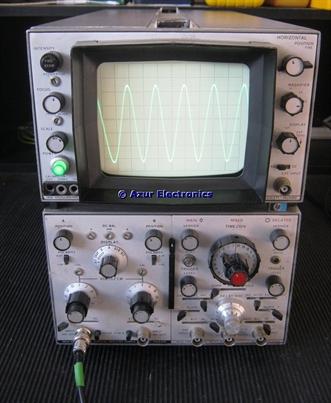
and 100MHz, magnifier x10, main timebase (right) display
+ve slope, dc coupled, mixed timebase (left) display
and 100MHz, magnifier x10, main timebase (right) display
Completed performance tests and adjustments.