
Welcome to
Azur Electronics
Azur Electronics
Home
Projects
Test Equipment
- Accessories
- Adaptors
- Amplifiers
- Attenuators
- Cables
- Frequency Counters
- Logic Analysers
- Multi-Meters
- Network Analysers
- Oscilloscopes
- Power Meters
- Power Supplies
- Prototyping Equipment
- Signal Generators
- Spectrum Analysers
- Tools
Operating Information
- Operating HP 141T
- Operating HP 1630D
- Operating HP 8175A
- Operating HP 8407A
- Operating HP 8410C
- Operating HP 8552B IF Section
- Operating HP 8553B RF Section
- Operating HP 8554B RF Section
- Operating HP 8555A RF Section
- Operating HP 8556A LF Section
- Operating HP 8594E Spectrum Analyser
- Operating HP 8901B
- Operating LeCroy 9310
Technical
- Allen Key Sizes
- High Voltage Measurement
- HP Cases
- HP Information
- HP-IB Interface Bus
- Measurement Units
- Motorola ECL
- RF Connectors
- RF Power - Voltage Conversion
For Sale
Wanted
Links
About Me
Contact Me
Site Map
REPAIR HP 8410C
NETWORK ANALYSER
NETWORK ANALYSER
March 2019
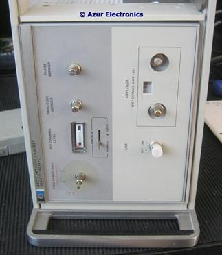
The HP 8410C Network Analyser is not showing an input level on the Ref Channel Level meter and there is no display on the 8412B.
Removing all the covers for access and inspecting the pcb's and wiring did not reveal any obvious faults.
Connecting up the system with the 8620C Sweep Generator, 86222A RF Section, 11667A Power Splitter, various attenuators, 8411A Harmonic Frequency Converter, to the 8410C with a 1GHz CW input. A 436A Power Meter, cable and 8481A Sensor was used to set the power levels at the 8411A Ref and Test Inputs to -24dBm and -12dBm respectively.
The 8411A input levels are: Reference -18dBm to -25dBm; Test -10dBm max. RF levels above -16dBm in the Reference channel and -10dBm in the Test channel will cause distortion in the 8411A preamplifiers. The input damage level is 50mW +17dBm ±3V dc. Plus the inputs are very sensitive to static, so ground cables before connecting them.
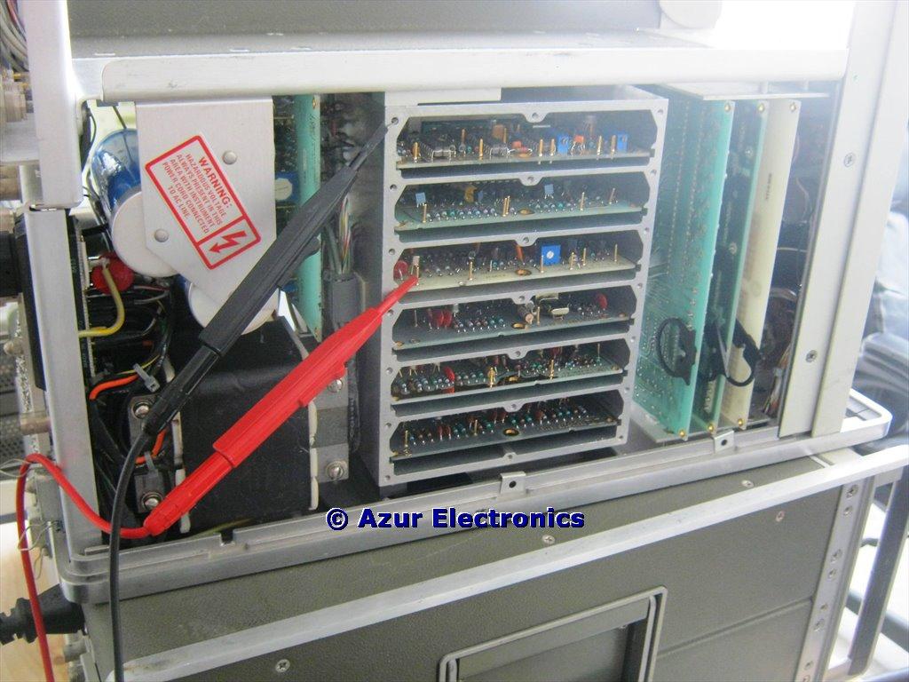
Top view with RF screened cover removed
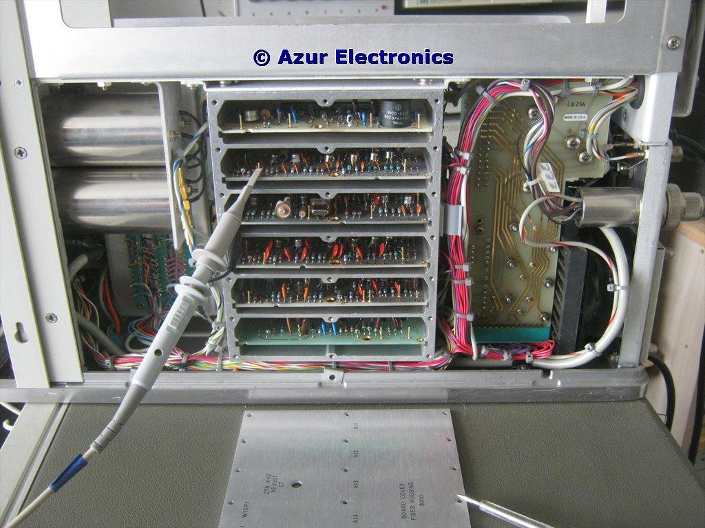
Bottom view with RF screened cover removed
April 2019
Started troubleshooting made easier by the test points available at the edge of the PCB's. Also have a PCB Extender Card available. Power supplies ok. Inputs from 8411A look ok. A7, A8, A9 assemblies checked. Some confusion with circuit dc levels due to illegability on some pages of the Manual.
July 2019
Checking through A11 and the amplifier output has -ve clipping. There is no ouput signal for the Test channel. Looks like a fault in the Attenuators A2S1 & A3S1. These are difficult to access and involves stripping the front panel down.
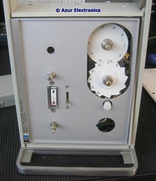
Front Panel & Escutcheon strip-down
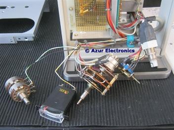
Front Panel Parts & Attenuators Assembly
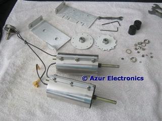
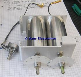
Attenuators carefully dismantled
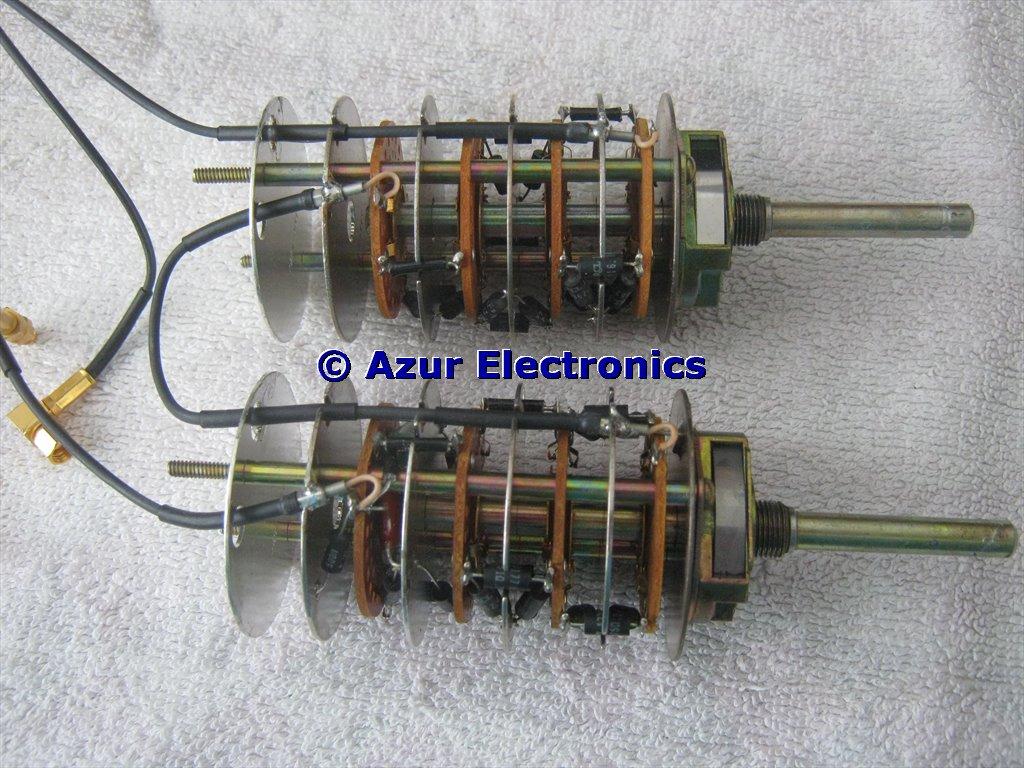
0-60dB & 0-9dB Attenuators
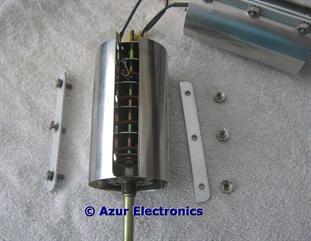
Cleaned up the Attenuators with contact cleaner and visually inspected, but no obvious faults. These are pi-type pads of combinations of 1dB, 2dB, 4dB, 10dB and 20dB. Plus there is an output LCR filter section. There is a short circuit on the output side which is loading the amplifier output. Removed the filter components and tested them ok. Refitting these showed a tiny short circuit to ground where the insulation sleeve was not quite long enough. Using SMC adaptors, connected up the Attenuators to a Signal Generator and Oscilloscope and all now working ok.
Reassembly is tricky and care is needed, especially to correctly align the attenuator scales. It took me 3 attempts to get it right!
Reassembly is tricky and care is needed, especially to correctly align the attenuator scales. It took me 3 attempts to get it right!