Welcome to
Azur Electronics
Azur Electronics
REPAIR HP 8553B RF SECTION
Home
Projects
Test Equipment
- Accessories
- Adaptors
- Amplifiers
- Attenuators
- Cables
- Frequency Counters
- Logic Analysers
- Multi-Meters
- Network Analysers
- Oscilloscopes
- Power Meters
- Power Supplies
- Prototyping Equipment
- Signal Generators
- Spectrum Analysers
- Tools
Operating Information
- Operating HP 141T
- Operating HP 1630D
- Operating HP 8175A
- Operating HP 8407A
- Operating HP 8410C
- Operating HP 8552B IF Section
- Operating HP 8553B RF Section
- Operating HP 8554B RF Section
- Operating HP 8555A RF Section
- Operating HP 8556A LF Section
- Operating HP 8594E Spectrum Analyser
- Operating HP 8901B
- Operating LeCroy 9310
Technical
- Allen Key Sizes
- High Voltage Measurement
- HP Cases
- HP Information
- HP-IB Interface Bus
- Measurement Units
- Motorola ECL
- RF Connectors
- RF Power - Voltage Conversion
For Sale
Wanted
Links
About Me
Contact Me
Site Map
November 2006
The HP 8553B RF Section has significant damage to the Front Panel, front left hand side, and front bottom of the unit. Initial inspection shows only obvious mechanical damage, so hopefully electrically it will be ok.
The HP 8553B RF Section has significant damage to the Front Panel, front left hand side, and front bottom of the unit. Initial inspection shows only obvious mechanical damage, so hopefully electrically it will be ok.
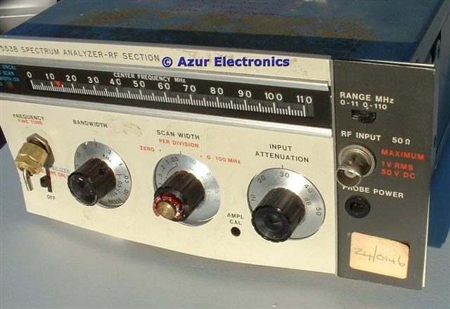
Front view showing broken knobs, bent panels, and squashed connectors

Looks even worse from top and bottom !
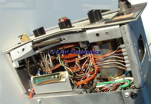
Started stripping down the 8553B, taking lots of notes and photos to aid re-assembly. There is no obvious damage to the rear 2/3 as it is a mainly sealed RF box. Removing a few screws from the front left hand and front right hand side panels, separates the front and rear sections, apart from the wiring.

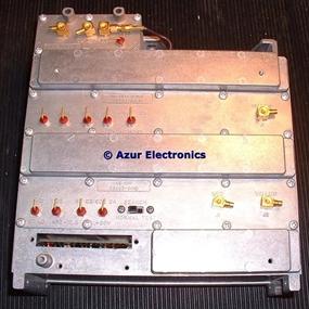
Top and bottom views of undamaged RF box
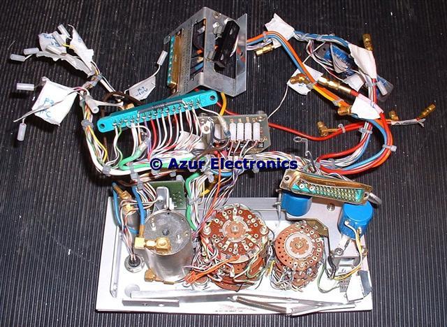
Removing all the wiring from the rear section leaves just the electronics housed in the RF shielded die-cast box, top view to the left and bottom view to the right.
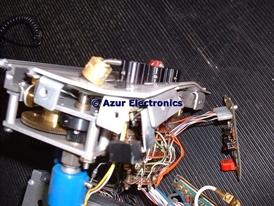
Rear view of front panel and wiring
The Front Panel can now be dismantled to get access to the damaged parts.

Damaged front panel and D connector
Obvious damage to the Front Panel and D-type connector to be repaired.
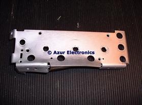

Damaged Escutcheon and Front Panel
The Escutcheon and Front Panel can now be straightened out in between wood blocks in a vice. This takes time but the shape can be restored.

The bent shaft for the Frequency and Fine Tune controls is beyond repair. This has an inner and outer shaft which is completely seized from bending. This also has a complicated gear mechanism attached to it to drive the 2 Variable Resistors, plus the cord and pulleys for the Centre Frequency Pointer. The shaft had to be sawn off to enable the gears to be separated. Will need to find replacement parts for this assembly.
December 2006
Further work on stripping down Front Panel parts and repairing the D-type and BNC connectors.
January 2007
Made up wood templates and straightened out various metalwork using G clamps.
March 2007
Bought Allen Keys to remove the control knobs. My cheap set were not accurate enough at the 0.050" and 1/16th inch sizes required. It is easy to round off the heads of allen screws by using slightly the wrong size of key.
November 2007
Managed to find a replacement dial extrusion with the variable resistors, gears, etc, from a scrap 8554B (thanks Robert) and some replacement control knobs. Using parts from both units enabled one complete assembly to be made up. Tricky to get everything set up correctly for inter-action between the 2 variable resistors, the gears and the dial pointer. Front Panel and parts all re-assembled then fitted to the rear section ok.
Completed the re-assembly ok. Controls are now all functioning correctly. Some slight mechanical distortion still, but much better than the condition it arrived in. Next task is performance testing when the rest of the Spectrum Analyser (141T, 8552B, 8555A) has been tested.
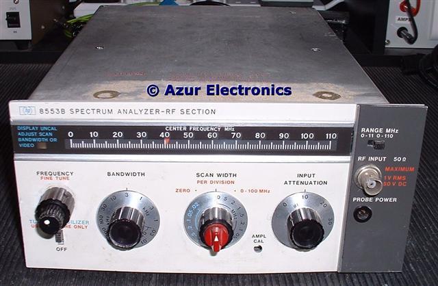
Front view of repaired unit
February 2009
After a 15 month delay, finally have the opportunity to test the 8553B. Powered up ok on a Variac. Some intermittancy between the D-type mating connectors for the IF and RF Sections needed some mechanical adjustment. This is a critical area for this equipment and often a cause of problems. It is fairly easily identified by the 'Log Ref Level' lamps on the IF Section not lighting up, as these are actually controlled from the Input Attenuator of the RF Section via the mating connectors.
Initial tests are all ok and the 30MHz Cal Output from the 8552B is correctly displayed in all modes. Operational adjustments show up a few minor problems: the Amplitude Calibrate control is out of line with the adjustment hole; the Display Uncalibrate lamp is not working; and the Centre Frequency Pointer is slightly out of position. Unfortunately this involves stripping the front panel down again!
The Amplitude Calibrate control is fixed by a single screw so it can rotate, although there is not much spare space behind the front panel. Adjusted so it lines up with the hole.
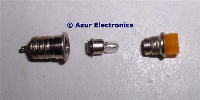
The Display Uncalibrate Lamp DS1 is driven from the A5 Assembly in the 8552B IF Section. Lamp On is -8V and Lamp Off is 0V via Plug P2 pin 10. The lamp is blown, so with no load the 'on' voltage is about -12V. Why did HP use so many different styles of lamps? Given a replacement lamp (many thanks Clive) and refitted.
Even with the Front Panel dismantled it is not easy to move the Centre Frequency Pointer. I decided to leave it alone as a minor issue, it is quite easy to measure the frequency accurately with a frequency counter anyway.
The Operational and some of the Performance tests now carried out successfully.
Put all the covers back on and typical, it didn't work anymore! No trace at all. Covers off and rechecked P3 (mating connector to IF Section). Now got a trace back but 40dB attenuation in vertical signal. This turned out to be the 50MHz output signal which also goes via P3 on one of the coax connections. Again an intermittant connection on P3. Soak tested for a few hours and all ok. When using this RF Section in the Spectrum Analyser will have to check out this mating connection before use. Not a problem (so far) with the other RF & LF Sections, so probably due to some slight mechanical distortion with the P3 connector and bracket.
July 2018
Have now acquired the HP 11592-60015 Plug-In Extender Assembly and HP 11592-60016 Inter-Connecting Cable. These make maintenance much easier.
Have now acquired the HP 11592-60015 Plug-In Extender Assembly and HP 11592-60016 Inter-Connecting Cable. These make maintenance much easier.