Welcome to
Azur Electronics
Azur Electronics
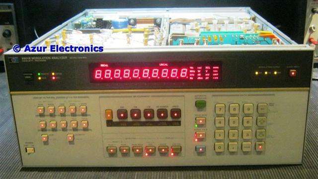
REPAIR HP 8901B
MODULAION ANALYSER
MODULAION ANALYSER
Home
Projects
Test Equipment
- Accessories
- Adaptors
- Amplifiers
- Attenuators
- Cables
- Frequency Counters
- Logic Analysers
- Multi-Meters
- Network Analysers
- Oscilloscopes
- Power Meters
- Power Supplies
- Prototyping Equipment
- Signal Generators
- Spectrum Analysers
- Tools
Operating Information
- Operating HP 141T
- Operating HP 1630D
- Operating HP 8175A
- Operating HP 8407A
- Operating HP 8410C
- Operating HP 8552B IF Section
- Operating HP 8553B RF Section
- Operating HP 8554B RF Section
- Operating HP 8555A RF Section
- Operating HP 8556A LF Section
- Operating HP 8594E Spectrum Analyser
- Operating HP 8901B
- Operating LeCroy 9310
Technical
- Allen Key Sizes
- High Voltage Measurement
- HP Cases
- HP Information
- HP-IB Interface Bus
- Measurement Units
- Motorola ECL
- RF Connectors
- RF Power - Voltage Conversion
For Sale
Wanted
Links
About Me
Contact Me
Site Map
October 2011
The HP 8901B Modulation Analyser initial testing indicates a problem. Powered up, fan running, all front panel displays on, then goes to FREQ, then all displays on again. After 10 minutes smoke started coming out of the unit so switched off. More work required when I have time!
December 2014
3 years later and with the 8901B cleaned up, start fault finding. Outer panels removed and plastic cover over PSU. A12 Assembly slot is empty which is normal, this is for Option 030 which is A71 IF Channel Filter and A72 IF Amplifier/Detector.
All front panel displays remain on
On power-up all the front panel displays remain on permanently.
DANGER: The front panel Power Standby/On switch does not switch the mains voltage! This means that high voltages are exposed around the power supply A26 & A10 Assemblies whenever the 8901B is connected to mains power.
DANGER: The front panel Power Standby/On switch does not switch the mains voltage! This means that high voltages are exposed around the power supply A26 & A10 Assemblies whenever the 8901B is connected to mains power.
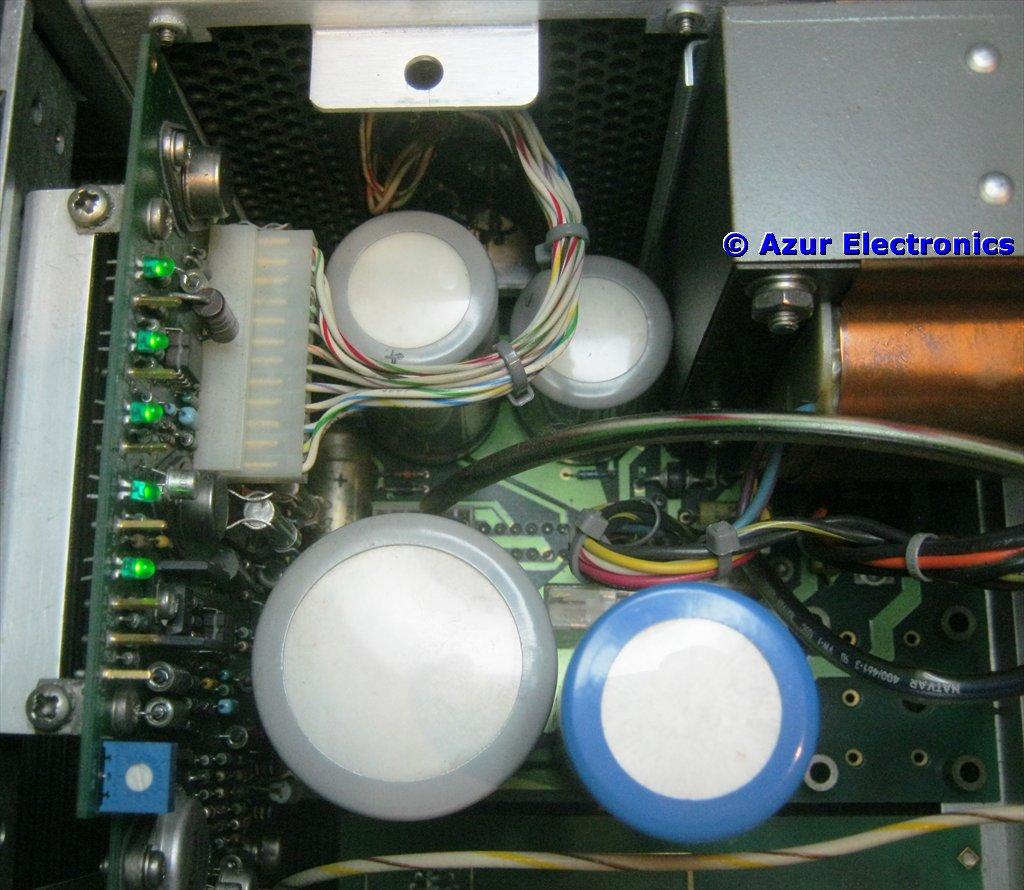
Power Supply 5 LEDs on A10
Suspected that the power supplies would be faulty but all ok. Green LEDs on the A10 Assembly indicate +15V -15V +5V -5V +40V. Checked dc levels, ripple and regulator inputs were correct.
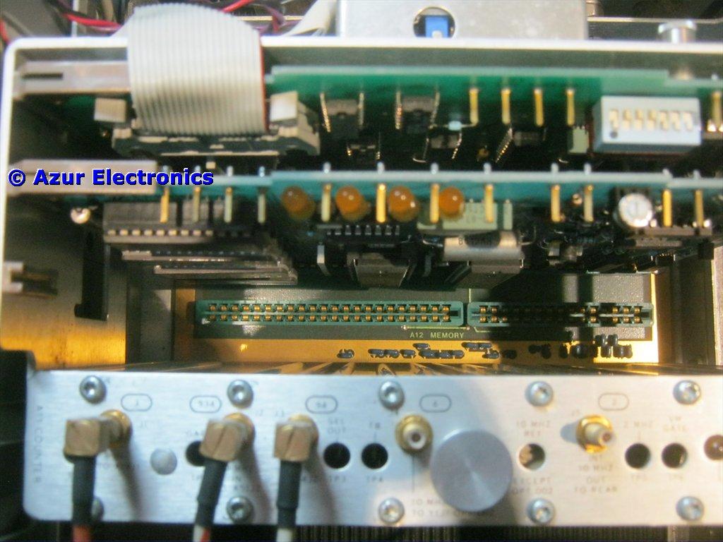
Power Up Check 4 LEDs on A13
The 4 Yellow LEDs on the A13 Controller Assembly indicate a power up sequence A B C D. This is not operating correctly with C initially flashing, indicating a RAM failure.
Soak tested for 15 minutes and the front panel displays all remain on but no more smoke! Whatever caused the smoke must have burnt itself out.
Soak tested for 15 minutes and the front panel displays all remain on but no more smoke! Whatever caused the smoke must have burnt itself out.
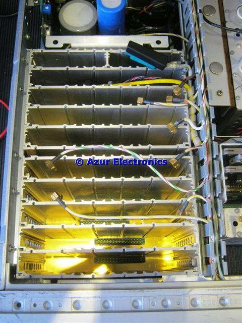
LHS RF Screened Housing
Removed all the individual PCB Assemblies, this involves a lot of TORX screws fixing the panels to the RF screened housings. Inspected all the PCBs but nothing found except a broken thermistor and some excess solder flux. So whatever caused the smoke has left no residual evidence, frustrating! I had expected to find a burnt out resistor somewhere. Refitted all the PCB assemblies.
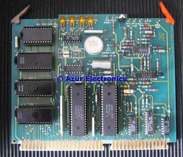
A13 Controller PCB
Checked various dc levels on the A13 Controller and the signals to/from the RAM, all ok so maybe the RAM has failed. This is a Toshiba TC5517APL so ordered 2 spares on eBay (must have been obsolete for many years). This is a CMOS part.
Replacement RAM arrived and fitted, this is U1 at the top LHS of the PCB. Powered-up and now all working. This is the first time that I have known a RAM to fail. Will keep a spare RAM just in case!
Work through the Operating and Calibration Manual, Basic Operation and Applications Guide from page 65 to check some of the measurement functions.
Correct Start Display
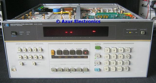
On power-up and with no signal input, all the front panel displays are on for 10s approx., then go to this state with 2 dashes and the MHz display. This is now correct.
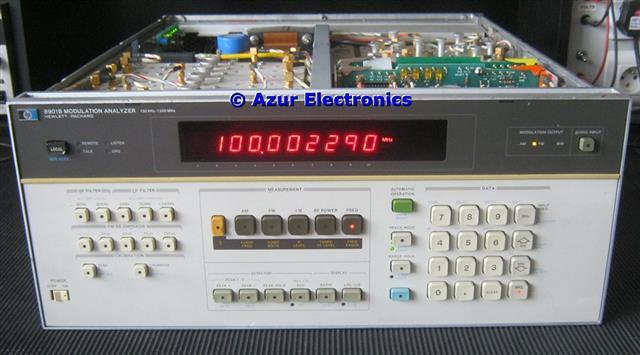
Normal Frequency Measurement
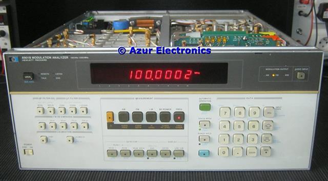
With a 100MHz signal connected, this is the correct display to 100Hz resolution.
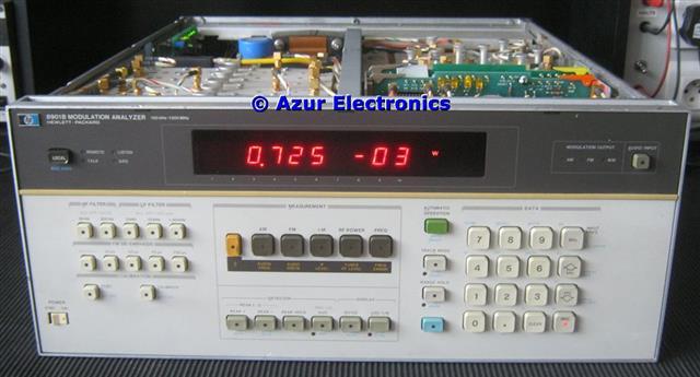
Normal Power Measurement
With a 100MHz signal connected and without an external power sensor, this is the correct display in Watts. Measurement in dBm is also available. Calibrated power measurements can be made using the 848X series of Power Sensors.
Special Frequency Measurement
With a 100MHz signal connected, this is the correct display to 1Hz resolution by using the Special Function Keys.
With the 8901B now repaired, all of the measurement functions will be checked.
October 2022
On power-up all the front panel indicators remain on. The 5 green power LEDs were all ok, but the 4 yellow status LEDs were incorrect. Turned out to be a problem with A14 Remote Interface Assembly not seating properly in the motherboad connector, probably due to the recent house move.
Also the green LED for the +15V supply subsequently failed. This has a zener diode, resistor and LED across the power rail. Replaced the LED and all ok.
Retesting after repair