Welcome to
Azur Electronics
Azur Electronics
HP 141T DISPLAY SECTION
EXTERNAL CONNECTIONS
EXTERNAL CONNECTIONS
Home
Projects
Test Equipment
- Accessories
- Adaptors
- Amplifiers
- Attenuators
- Cables
- Frequency Counters
- Logic Analysers
- Multi-Meters
- Network Analysers
- Oscilloscopes
- Power Meters
- Power Supplies
- Prototyping Equipment
- Signal Generators
- Spectrum Analysers
- Tools
Operating Information
- Operating HP 141T
- Operating HP 1630D
- Operating HP 8175A
- Operating HP 8407A
- Operating HP 8410C
- Operating HP 8552B IF Section
- Operating HP 8553B RF Section
- Operating HP 8554B RF Section
- Operating HP 8555A RF Section
- Operating HP 8556A LF Section
- Operating HP 8594E Spectrum Analyser
- Operating HP 8901B
- Operating LeCroy 9310
Technical
- Allen Key Sizes
- High Voltage Measurement
- HP Cases
- HP Information
- HP-IB Interface Bus
- Measurement Units
- Motorola ECL
- RF Connectors
- RF Power - Voltage Conversion
For Sale
Wanted
Links
About Me
Contact Me
Site Map
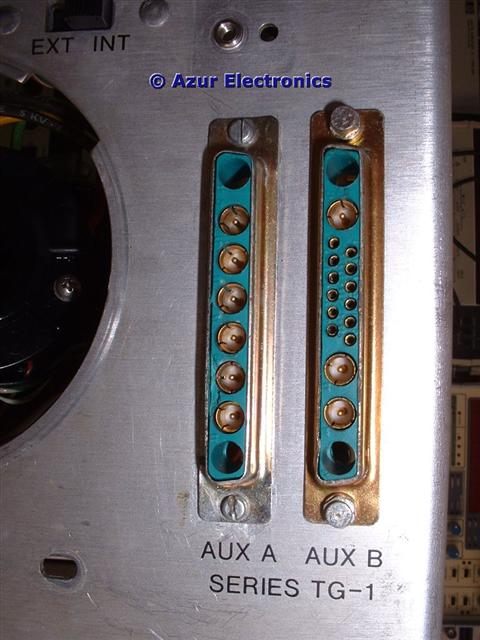
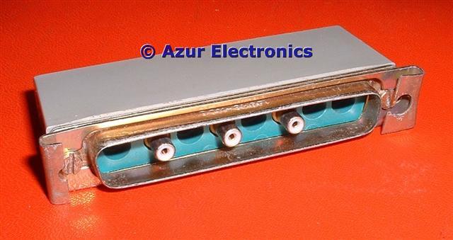
These 2 special D-type connectors on the Rear Panel are labelled AUX A (J8) and AUX B (J10).
They are wired to J9 and J11 inside the 141T and mate with the HP 8553B RF Section, HP 8554B RF Section or HP 8555A RF Section. For details see HP 141T Display Section Internal Connections.
Externally, AUX A is connected to either the HP 8443A Tracking Generator Counter or the HP 8444A Tracking Generator and AUX B is connected to the HP 8445B Automatic Preselector.
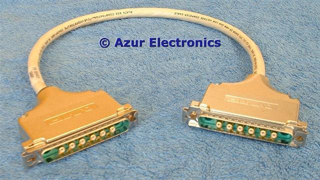
Special cable 08443-60009 for connecting AUX A to the 8443A Tracking Generator. This cable is available from GLK Instruments.
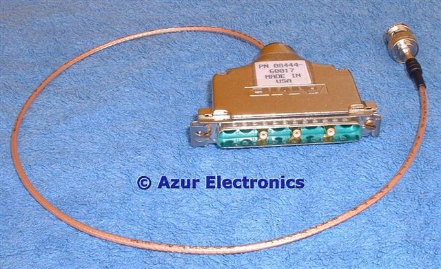
Special cable 08444-60017 for connecting AUX A to the 8444A Tracking Generator. This cable is available from GLK Instruments.
Additional BNC to BNC cables are required to connect the 8554B (2 required) or 8555A (3 required) to the 8444A.
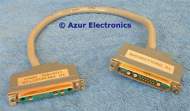
Special cable 08445-60007 for connecting AUX B to the 8445B Automatic Preselector. This cable is available from GLK Instruments.
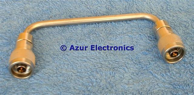
Special cable 08445-20022 for connecting 8445B output to 8555A input. This is a rigid N-type coaxial cable. Very difficult to obtain!
|
RF & LF Plug-In Units |
Frequency Range |
Tracking Generator |
Special Cable |
|
8553B RF Section |
1kHz to 110MHz | 8443A | 08443-60009 |
|
8554B RF Section |
100kHz to 1,250MHz | 8444A | 08444-60017 |
|
8555A RF Section |
10MHz to 18GHz |
8444A up to 1,300MHz |
08444-60017 |
|
8556A LF Section |
20Hz to 300kHz | Included | None |
NOTE: Only the 8555A will operate with the 8445B Automatic Preselector.
AUX A Connections
|
J8 Top |
|
8443A Functions |
8444A Functions |
|
A1 |
n.c. | Guide Pin | Guide Pin |
|
A2 |
RD |
1st Local Oscillator 200MHz to 310MHz |
3rd Local Oscillator 500MHz |
|
A3 |
OR |
Scan Voltage 0V to 10V |
Scan Voltage 0V to 10V |
|
A4 |
YL |
2nd Local Oscillator 150MHz |
Local Oscillator 47MHz |
| A5 | GY | 3MHz IF * |
Sweep + Tune/Full Scan -5V to -10V |
| A6 | BL |
3rd Local Oscillator 47MHz |
Tuning Stabiliser Enable |
| A7 | VL |
Centre: Blanking Shield: Zero Scan |
Centre: Blanking Shield: Zero Scan |
| A8 | n.c. | Guide Pin | Guide Pin |
| J8 Bottom | 8443A Functions | 8444A Functions |
NOTES:
The connecting cable to the 8444A only uses the A2 500MHz connector.
A4 and A6 are terminated in 50Ω.
* The 3MHz IF is not used on S/N <1144A.
The connecting cable to the 8444A only uses the A2 500MHz connector.
A4 and A6 are terminated in 50Ω.
* The 3MHz IF is not used on S/N <1144A.
If the special cables to the 8443A or 8444A are not used, then the A2 A4 & A6 outputs at Aux A should be terminated with the 08553-60122 50 Ohm Termination. This applies for all the RF Sections but is not required for the LF Section.
AUX B Connections
|
J10 Top |
|
8445B Functions |
|
A1 |
n.c. | Guide Pin |
|
A2 |
WH |
50MHz IF |
|
Pin 1 |
914 |
'A' Bit Band Code |
|
Pin 7 |
924 |
YIG Tune Voltage |
| Pin 2 | 915 |
'B' Bit Band Code |
| Pin 8 | 925 |
not listed |
| Pin 3 | 916 |
'C' Bit Band Code |
| Pin 9 | 926 | not listed |
| Pin 4 | 917 | 'D' Bit Band Code |
| Pin 10 | 927 | not listed |
| Pin 5 | 918 | 'E' Bit Band Code |
| Pin 11 | 902 | +20V |
| Pin 6 | 923 | not listed |
| Pin 12 | 0 | +20V Return |
| A3 | BL | Sweep + Tune/Full Scan -5V to -10V |
| A4 | RD | Per Division Sweep |
| A5 | n.c. | Guide Pin |
| J8 Bottom | 8445B Functions |
NOTES:
All these connections will be investigated further when the individual units are tested, especially the connections marked not listed.
On the 8445B the coax connections for A4 and A2 are not fitted in the D-type connector.
All these connections will be investigated further when the individual units are tested, especially the connections marked not listed.
On the 8445B the coax connections for A4 and A2 are not fitted in the D-type connector.
August 2019
Have now sold all my 141T based equipment.
Have now sold all my 141T based equipment.